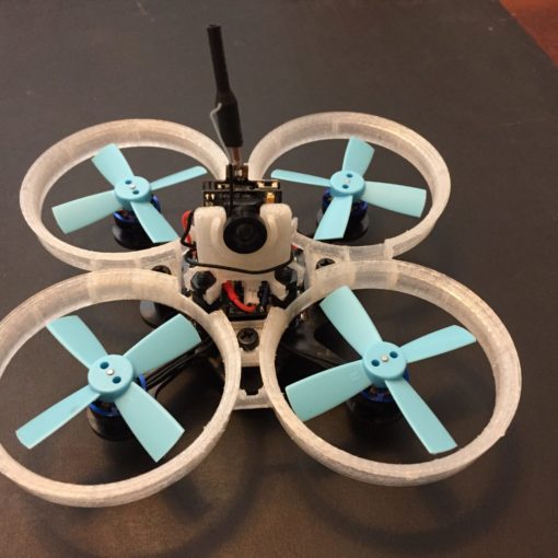
Walkera has proven to be a solid contender in the quadcopter market in recent years. If you own a Devo 7e transmitter and want to control all your RC/drones from one device and also get a little more “oomph” to its signal and penetration, you’ve come to the right place.
In this guide, we will go through the process from start to finish of replacing your transmitter module and antenna in your Devo 7e.
First off, you’re going to have to acquire the parts needed for the modification.
List of required parts
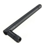
RP-SMA Antenna
.
This can be as basic or as complex as you need. We recommend a 3bdi antenna, but if you want something higher, it will work.
Hardware Installation
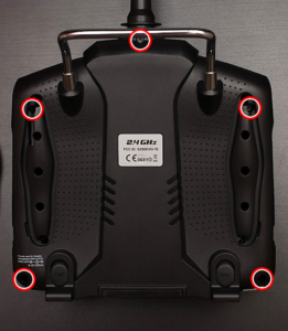
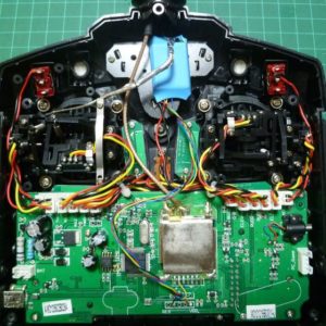
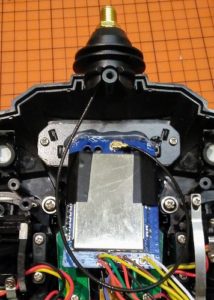
Open Devo 7e case
There are 5 screws on the back of the unit, one in each corner and one under the antenna.
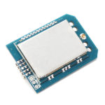
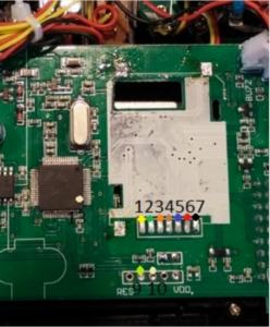
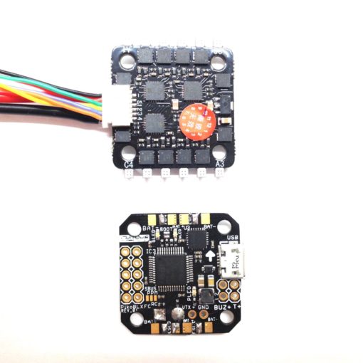
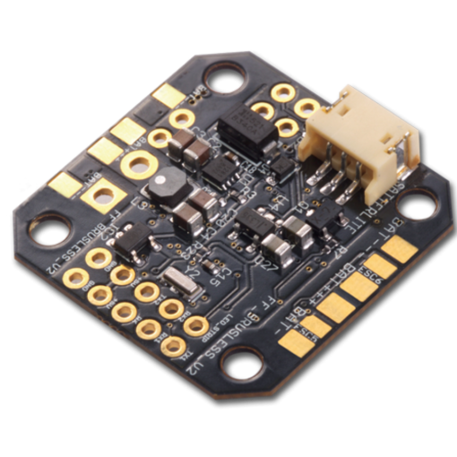
Remove stock transmitter module
The RF board sits in the middle of the unit. It has metal shielding over it.
Desolder the pins that hold it to the main board You may have to pry it off a little to dislodge the adhesive.
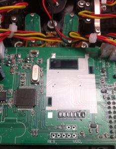
For most efficient removal slowly heat one side and gently apply lifting pressure with the flat screw driver, make sure not to do it very gently to avoid ripping off pads from the PCB.
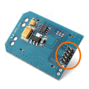
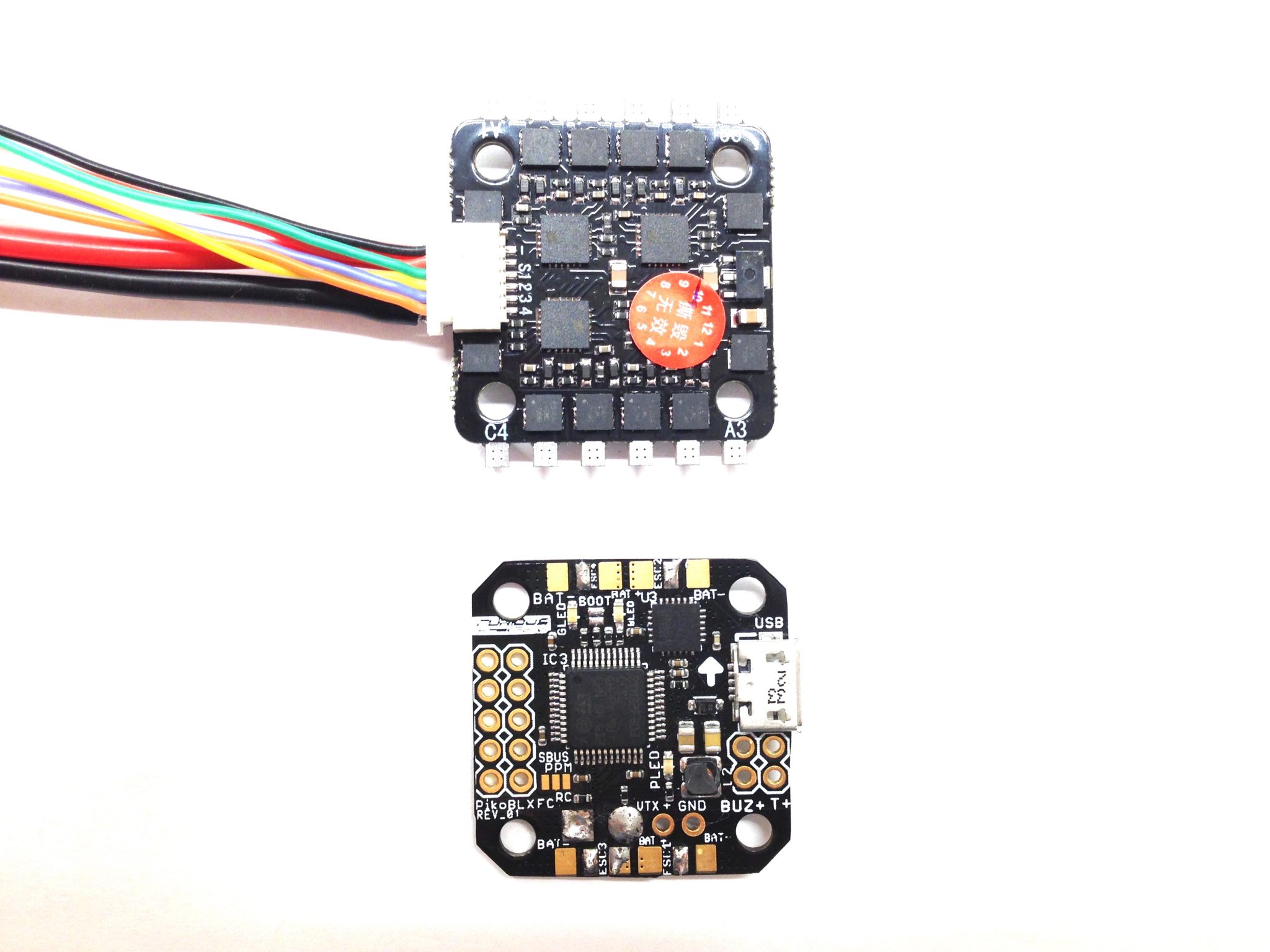
Remove pins from RF 4 in 1 module
Your new RF module should have pins, go ahead and desolder those so you have open solder points.
Install new transmitter module
Here comes the tricky part.
Once you have pads on both sides, solder your wires (about 6-8cm) from the RF module to the transmitter board according to the diagram provided below.
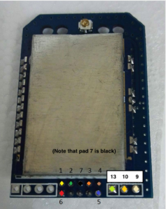
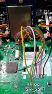
Using different colored wires is highly recommended as it makes it a lot harder to make a mistake.
Please note that pin #13 (from 4 in 1 module) should be connected pin #2 on the transmitter chip, the best way to do it is by isolating it with kapton tape:
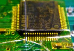
and then soldering the wire.
If you are in doubts and want to see a bit more pictures and how other people did it then you might find HappyHarry’s post in Deviation forum useful as well.
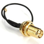
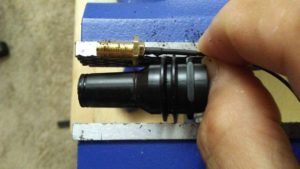
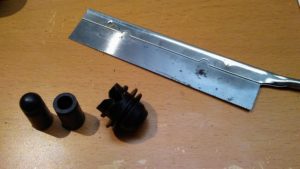
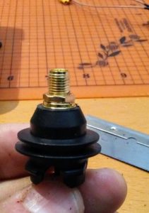
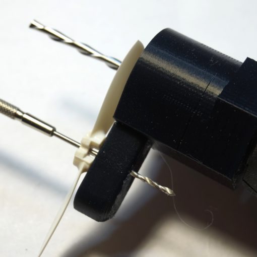
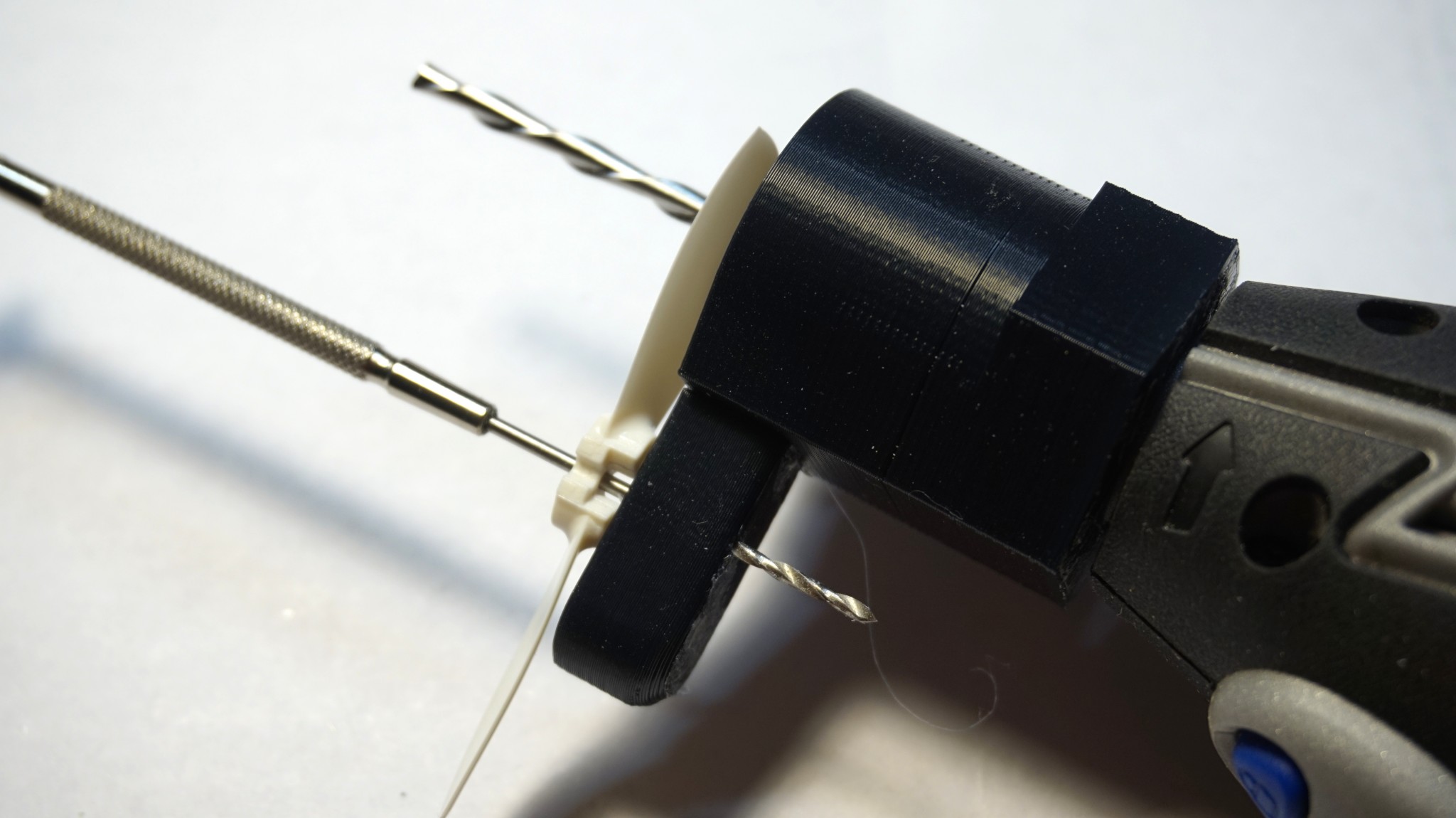
Install new antenna
Now that the electrical bit is done, we’re going to have to make room for the new antenna.
Start by removing the top part of the antenna, right where the taper begins, with a hobby saw.
Once that is off slip in your pigtail and tighten up, plug in the UFL connector, and you’re golden.
Put it back together
Reassemble everything and move on to the software tweeks!
Software
Download DFU USB tool
Go to https://www.deviationtx.com/downloads-new/category/161-dfu-usb-tool and download the DeviationUpload-0.8.0.jar Java app
Start Devo 7e in DFU mode
- Attach the 7e to your computer through USB
- Hold EXT and power up your Devo
Upload new configuration
- Launch the java app you just downloaded: DeviationUpload-0.8.0.jar
- Click “File Manager” tab
- Double-click the “HARDWARE.INI” file
- Copy/paste the following configuration:
;Only useful for transmitters with an after-market vibration motor

;enable-haptic=1

;

;switch_types: 3x2, 3x1, 2x2

;extra-switches=

;

;button_types: trim-all, trim-(left|right)-(up|down|both)

;May occur more than once if necessary.

;extra-buttons=

;

[modules]

; there is no need to enable the cyrf6936 module unless

; it is wired to an alternate port. It is Enabled automatically otherwise

; enable-cyrf6936 = B12

  has_pa-cyrf6936 = 1

  enable-a7105    = A13

  has_pa-a7105    = 1

  enable-cc2500   = A14

  has_pa-cc2500   = 1

  enable-nrf24l01 = A15

  has_pa-nrf24l01 = 1

; enable-multimod = A13 - Click File – “Save”
- You might get a dialog telling you to sync your filesystem; click “OK”
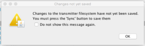
- If you get a prompt to sync the filesystem, click OK (Round button with circular arrows)
Congratulations! You’re done! Go sync up your receivers and fly!
(thanks to Hacksmods, HappyHarry, burtlo and various RC Groups users for the photos!)