Owl + ArduPilot, really?
When you step into the land of custom and self-invented solutions, experiments can lead you to some strange things, you know 🙂 So here I’d like to share my experience with building a drone based on beautiful Owl frame by FlexRC and Ardupilot-driven flight controller.
This is indeed strange configuration at first glance, as Ardupilot, and especially flight controllers running it, look like a great overkill for such small nice and nifty Owl, and this is probably so. But… it also opens a range of additional options and possibilities (though small flight controllers and their firmware features are constantly grow and chase feature parity): automated flights with complex programming, some complex flight modes, ability to use digital camera as FPV through GStreamer and telemetry, and, the most valueable for me, ability to run custom programs without any restrictions of microcontrollers, to perform analysis, image recognizion, measurements and movements with GPIO etc. So I ordered all the necessary parts for Owl, grabbed my Navio2 hat for Raspberry Pi 3 and started to build.
First touch
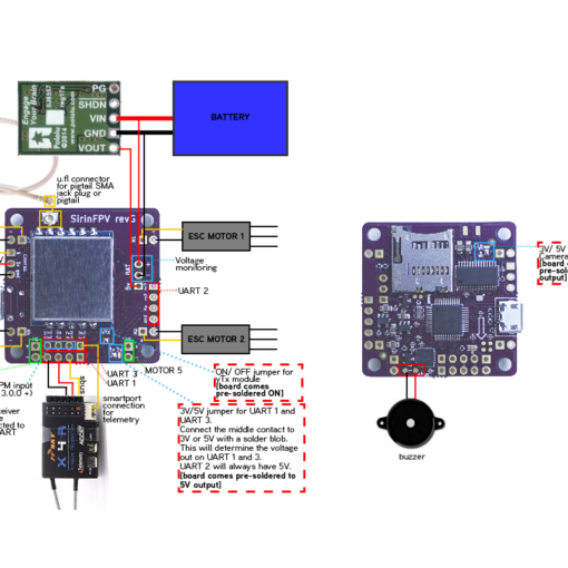
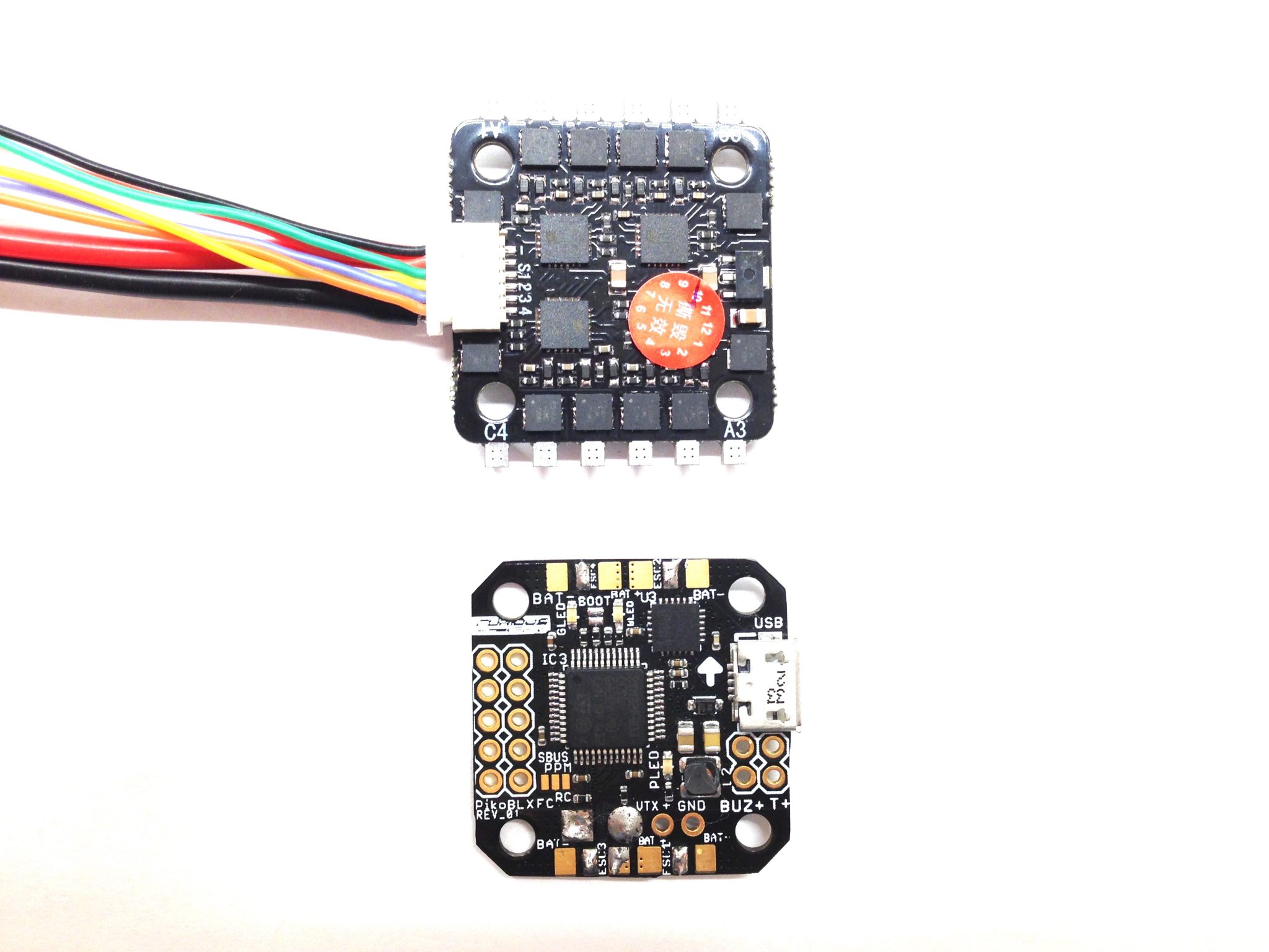
WIth Owl frame itself I also ordered 4-in-1 ESC based on BB2 and BLHeli_S-driven and 4 pieces of T-Motor F20 4100kv. As all these guys are from microworld, I needed to plug it some way to my components from ‘ordinary’ drones. ESC signals happened to connect just fine to PWM outputs via 2.54 mm plugs (OK, I know, they’re to be soldered, but, please, forgive me for this :). And for power connections I grabbed several XT60 males and females. Don’t know, if it’s on purpose or not, but a construction hole in the upper plate of Owl is ideally sized to put XT60 through it.
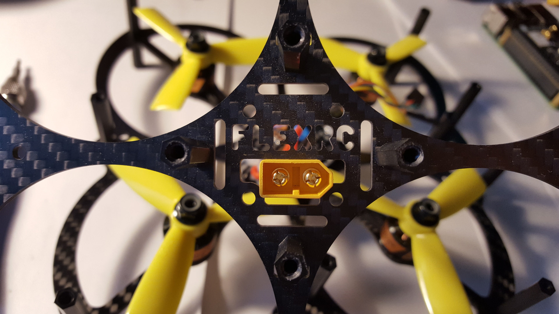
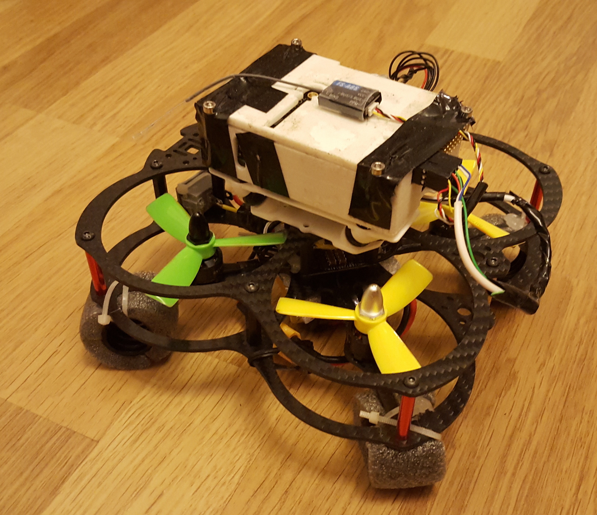
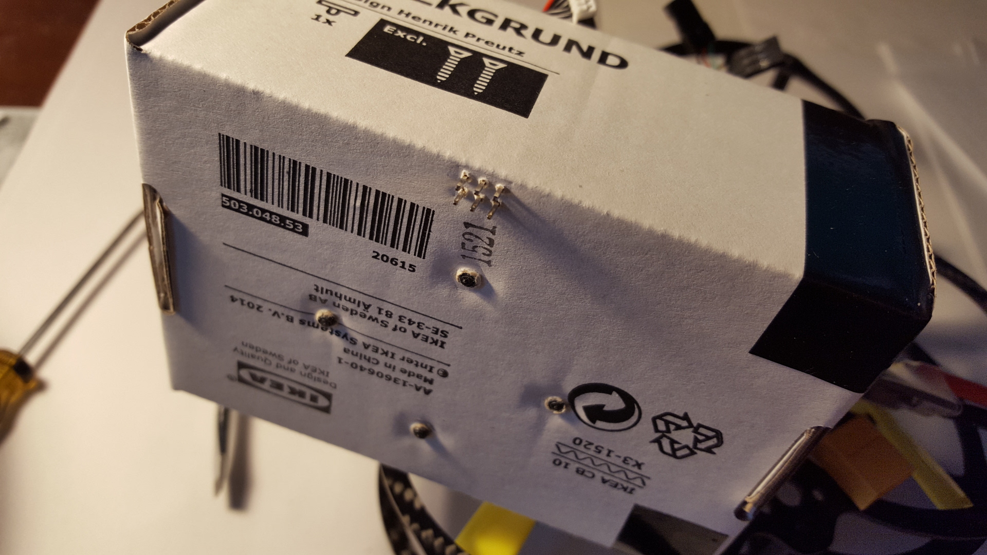
In any case, it couldn’t be overstated, how good it was for my first version of the drone, as I had no option, but to install everything on top of the drone, so I needed to put the wires to top somehow. Without this magic hole I’d need to unsolder and re-solder XT60 with each taking away of upper frame plate. I used quite common APM power module to power my flight controller. In terms of the setup for the first version I just put all the gear (flight controller, RC receiver, battery, power module) to some paper box I had of some Ikea thing, which was installed using nylon spacers on top of the Owl.
I managed to let it to take off, but soon key problems of this construction became visible.
Construction problems
- The first clear point was the weight, which exceeded 500 g. It surely was able to take off (at about 55% of throttle) and even quite fast, even on 3S, but the flight was really unstable. There weren’t some particularly clear ways to decrease it, but it obviously should be done.
- Another concern was the fragility of the whole setup. Paper box was too weak to resist any crashes, which were quite frequent due to the rest of the reasons.
- Another important problem was balance: place of the center of mass, which was too high due to the place of the heaviest components (FC and battery).
- The last concern was software one: Ardupilot initialization procedure led ESCs to calibration mode for some reason, so it wasn’t unusual, that one of ESCs got calibrated to some random levels when you just turn on your drone. That was real pain.
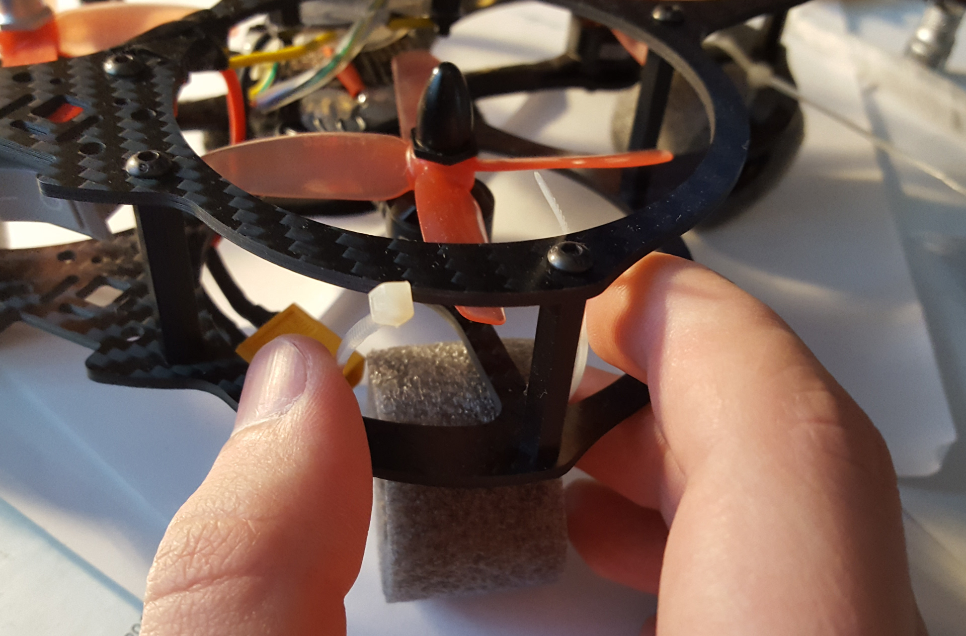
At first I added legs made of pipe heat insulation I got on the market near me. Initially I tried to use nylon spacers as legs, but they broke too frequently. Legs allowed me to move battery to the bottom space and move the center of mass lower. That indeed helped in terms of control.
Then I’ve updated Ardupilot to version 3.4 and sporadic calibration problem went away. But just before I soldered a USB 1-wire programmer for BLHeli_S-based ESC controllers. When you’re with some good micro flight controller, you obviously don’t need it with passthrough mode, but I don’t have this, so USB programmer was the only way to get access to ESC with BLHeli Suite.
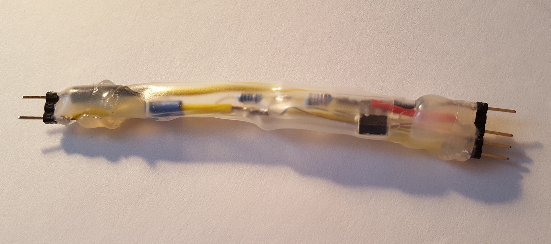
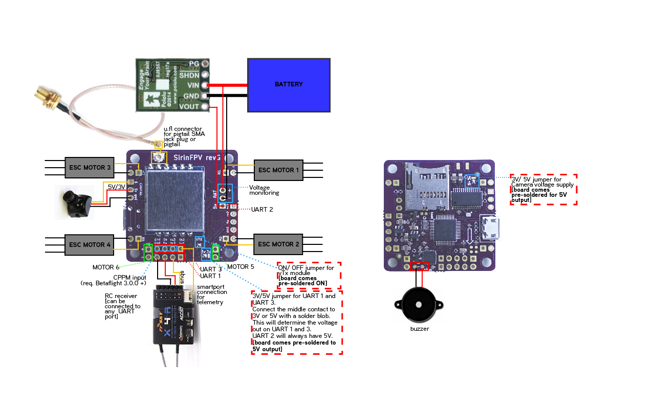
1-wire Programmer
In terms of schematic 1-wire adapter for any UART USB adapter is quite straightforward and explained quite good in the BLHeli Suite documentation and in these two posts. But I got stuck with it for a couple of days due to some subtle moments. I describe them here in case of anyone’s interested.
At first, there wasn’t any reference anywhere on what logic level is used, +5V or +3.3V. It’s just pointed, that VCC should be +5V, nothing else. Digging into SiLabs BB21 datasheet I learned, that indeed 3.3V should be used, but the chip port pins are 5V tolerant, so it’s safe to use 5V (ATTENTION: this is only valid for SiLabs BB21 chips — if you have another chip in you ESC, PLEASE consult the datasheet OR USE 3.3V). That was quite handy, as my FTDI-based USB-UART breakout has the only the 3.3V/5V switch, which switches both VCC and logic level, so if you want 5V on VCC, you also get 5V on signal pins, and if you want 3.3V signals, be satisfied with 3.3V on VCC. The only way to make it properly without 5V-tolerant ports is to use 5V mode and use another 5V-3.3V level conversion board.
Another key point was to connect TX and RX properly. My ridiculous story was in the fact, that DFRobot guys, my breakout board manufacturer, decided to “help” user a little bit and print the opposite marks on the board, i.e. FTDI’s RX become TX of the board, and TX become RX. So these marks probably mean “what to connect” to the corresponding pins. I didn’t noticed it until the last moment, so couldn’t connect to ESC for a long time. Please, read the datasheets carefully and keep in mind, that BLHeli Suite circuit describes the connections in terms of FTDI chip, not the whole UART board or something else. So trace it properly with two circuits to get the right connection.
Motor break
The rest of the problems look less important and far more difficult to solve, so I tried to fly on this built until I broke a motor. As for the motors, I should say, I personally don’t like T-Motor F20 too much. Maybe I suffered from some bad luck with a suite of them, but they didn’t look too confident at all. At the very beginning, two of my motors had small movement when you try to ‘bend’ the shaft sides, to test the bearing. In flight it looked like some flatter and abnormal vibration, which partially could be due to improper PID settings. That wasn’t too much a problem though, so I flew with it until one of the motors just broke. It was the shaft which broke, as I think, because of the propeller was slowed by a pillow (I learned to fly above my bed to eliminate crash results). The propeller flew away, broke the spacer of the frame, its own blades and another propeller. As a result I ordered two other sets of motors, one DYS 1306 4000kv, which I fly now on, and EMax 1306 4000kv, which I haven’t tried yet. For me, DYS and Emax look much more sturdy and durable, than T-Motor’s. I’m so happy with DYS I use now. There’s no movement or something. They feel a little heavier, but obviously DYS work just fine up until now (for a couple of months already), while T-Motors broke just after several weeks of experiments. FlexRC kindly offered me a replacement, but I just ordered a spare shaft of the same diameter and hope to bring the broken motor to life again.
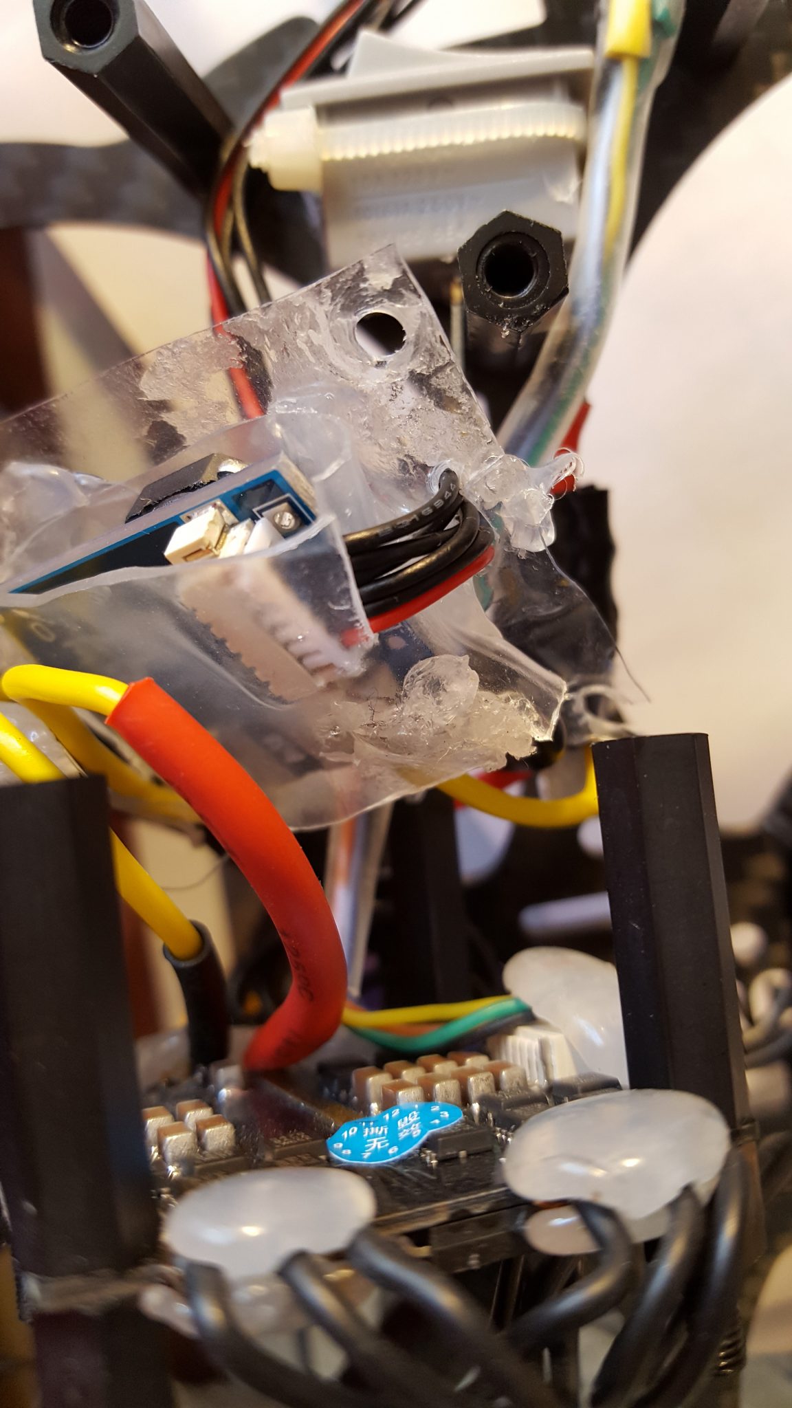
Version 2
Having a forced pause while the motors were on delivery, I changed the construction of my drone. I removed big thick wires from my power module (and it’s also a subject to change it to Matek PDB, this solution looks better than my DIY-based plate), added a switch to turn the drone on and off without detaching the battery, and put this electrical parts from the top basket to the middle of the drone. Then I changed the way the flight controller is installed: paper box was replaced with Navio2 case I’ve printed before, but didn’t use. I screwed cloth sticker to the frame and now the flight controller case is installed on this sticker. The construction became quite stable and more sturdy, but the flight controller suffered from vibration and several balancing issues remained.
Version 3
Final adjustment was installing anti-vibration platform for Navio2, which has the advandages of:
- it can be “officially” installed, as happened to have 36×36 mm hole pattern, and
- it really helps the stabilization, probably avoiding any vibrations to reach IMU
To solve the balance issues I’ve ordered several 30mm aluminium and brass spacers to install them instead of nylon ones in several places. The advantages of this are:
- They make the frame construction more durable and sturdy. Working with nylon things you might notice, that it’s really easy to screw off nut or spacer, and you can no more fasten it properly after this. Unless you’re Olympic winner, that is not the case with aluminium or brass pieces, even nylon bolts are handled easier with them.
- It’s more flexible to preserve the balance. For example, you can change nylon to aluminium spacer everywhere (they almost equal in weight), but to move the balance to some side, you can put a brass spacer there (which is much heavier). As we have about 3-4 points on each side of the drone on Owl frame, it’s quite easy to combine all types of spacers to get the proper balance and durability.
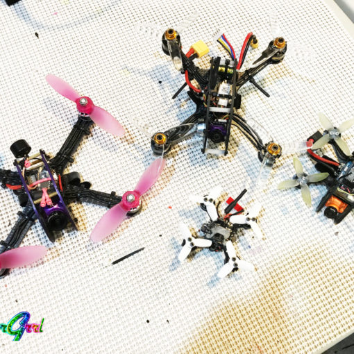
Another fine-tuning change I planned was to try different 3-blade and especially 4-blade propellers. My favorite set was actually my first DAL T3045BN. They are 3-blade, but so powerful and also quite smooth in the fly, which I like. 4-blade propellers looked significantly more powerful to me (i.e. it’s the change clearly visible), but it always seems, that the drone become more twitchy and sensible to your every lightest touch to the throttle stick. Among 4-blade props HQProps 3x3x4 taste the best to me, but I also tried Team Racecraft and 3035 Gemfan, which are also good. Again, I would say, that the latter two give you more power, which is a little harder to control, but if you can, you’re probably can get most out of it.
So, now the drone flies quite satisfactory for me. Of course, it’s not that on-the-edge racing drone, as with some micro-controller, but it’s still quite good indoor solution with the Ardupilot-based flight controller.
2 thoughts on “Ardupilot-driven Owl”
Great article, thanks for sharing!
Apparently T-Motors had a bad batch of 4100kv motors, and most likely you were affected by it. New batches should be much stronger.
I’d also think that it might be beneficial to try pusher configuration for such a heavy setup.
Thanks, Dmitry!
Yes, you’re probably right, I saw a lot of positive reviews of T-Motors, so it apparently was some random thing in my case. Thanks also for the idea of pusher configuration, I thought, they are just identical.