Download FlexRC Mini Owl – Extreme Omnibus – DIY Build Instructions
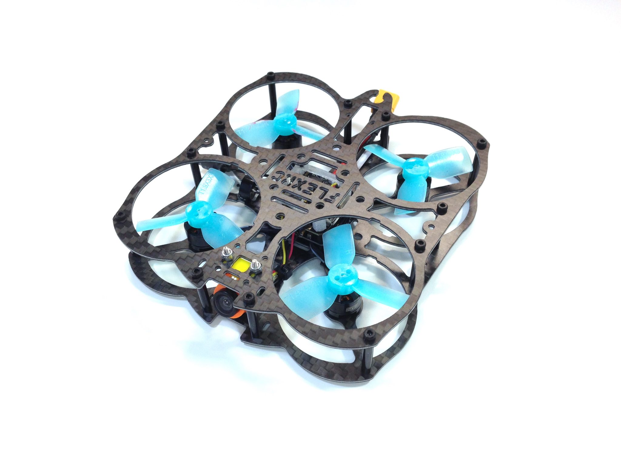
This guide will walk you through the detailed build steps using the FlexRC Mini Owl Extreme FPV Racing Drone DIY Kit. The kit contains everything you need to build your Mini Owl except the radio receiver, which is purchased as an add-on to the kit. In our example, we’ll be using the Lemon Rx DSMX Satellite Receiver. The instructions also include the installation of an optional Pololu voltage regulator.
The Mini Owl can be built as a pusher (motors “upside down”) or a standard (motors right side up) quadcopter. We’re building ours as a standard quadcopter. There is very little difference in the two builds other than motor directions and prop mounting.
The Kit:
- FlexRC Mini Owl frame with hardware
- Omnibus Mini F3 Flight Controller with OSD
- Tiny 10A 4 in 1 – Cicada – BusyBee2 BLHELI_S ESC
- 1pc of XT30 battery connector
- 1104 6500kv motors
- 2pcs of HQProp 1.9x3x3 Durable 3-Blade Propeller (2CW, 2CCW)
- DIATONE 600TVL Miniature Camera
- Flexible Mini Camera Adjustable Mount
- Tiny FPV Kit
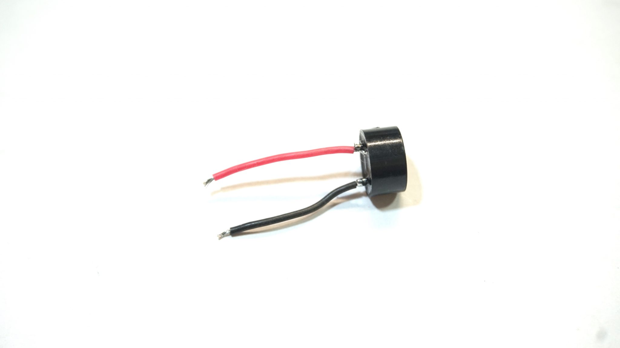
- 5V Mini Buzzer for FPV Micro Racing Drones
- Thin battery strap
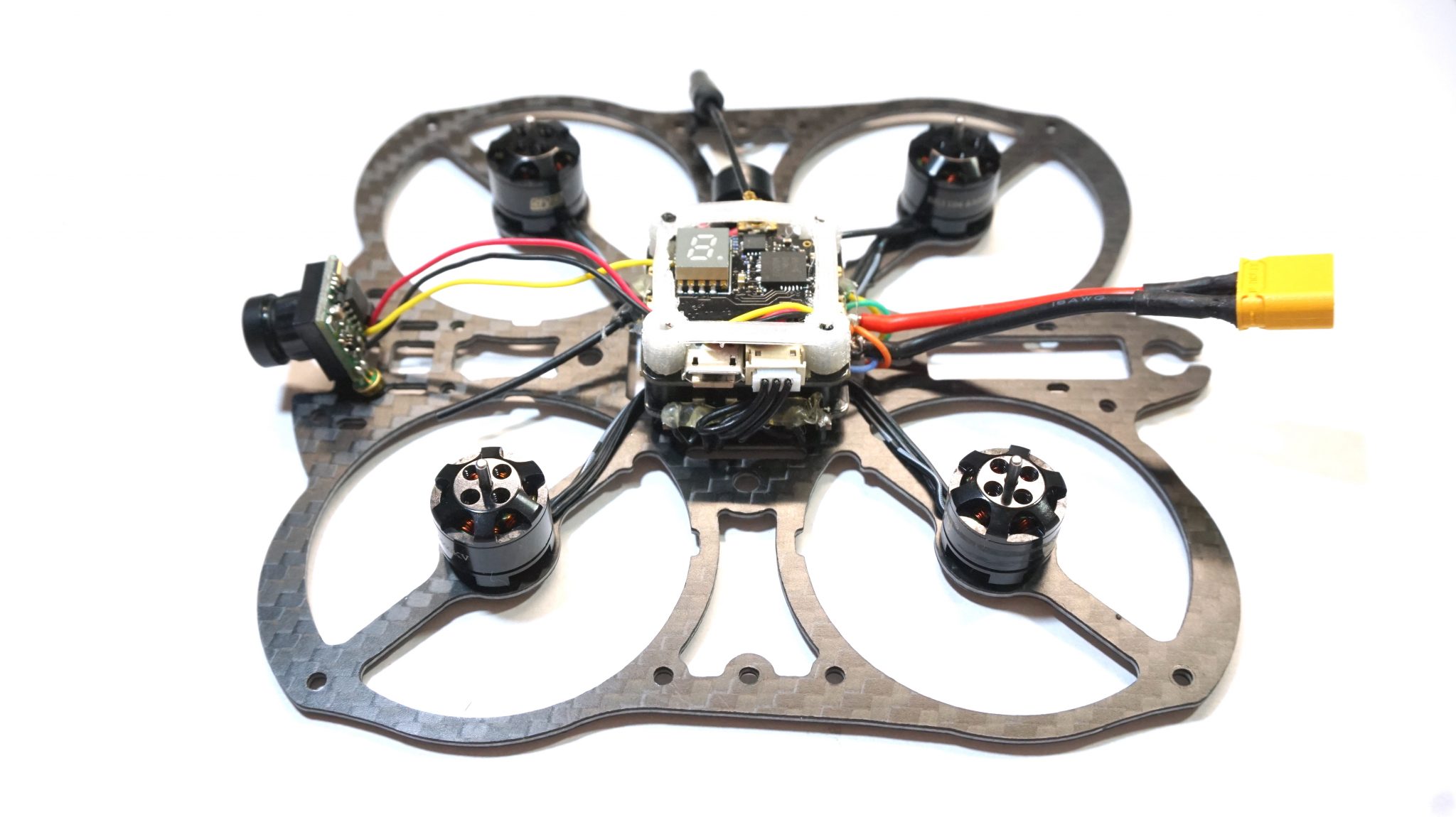
Step 1: Install the motors and center stack screws
Locate the bottom plate and mount each motor using the included motor mount screws. It is best to use all four screws to avoid having a motor pull out in a crash but, for now, it’s fine to just install two screws. We’re just using them to hold the motors in place during the installation at this point. Before flying, you should use Loc-Tite (blue) on all four screws.
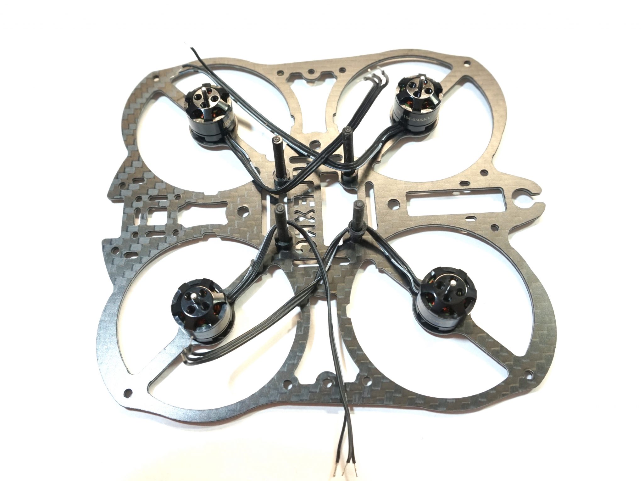
Leave the motor leads full length for now; we’ll trim them when we solder them to the ESC.
Next, install the nylon screws by pushing them through the 20×20 holes from the bottom of the frame. These will secure your center component stack. Place a nylon spacer on each screw.
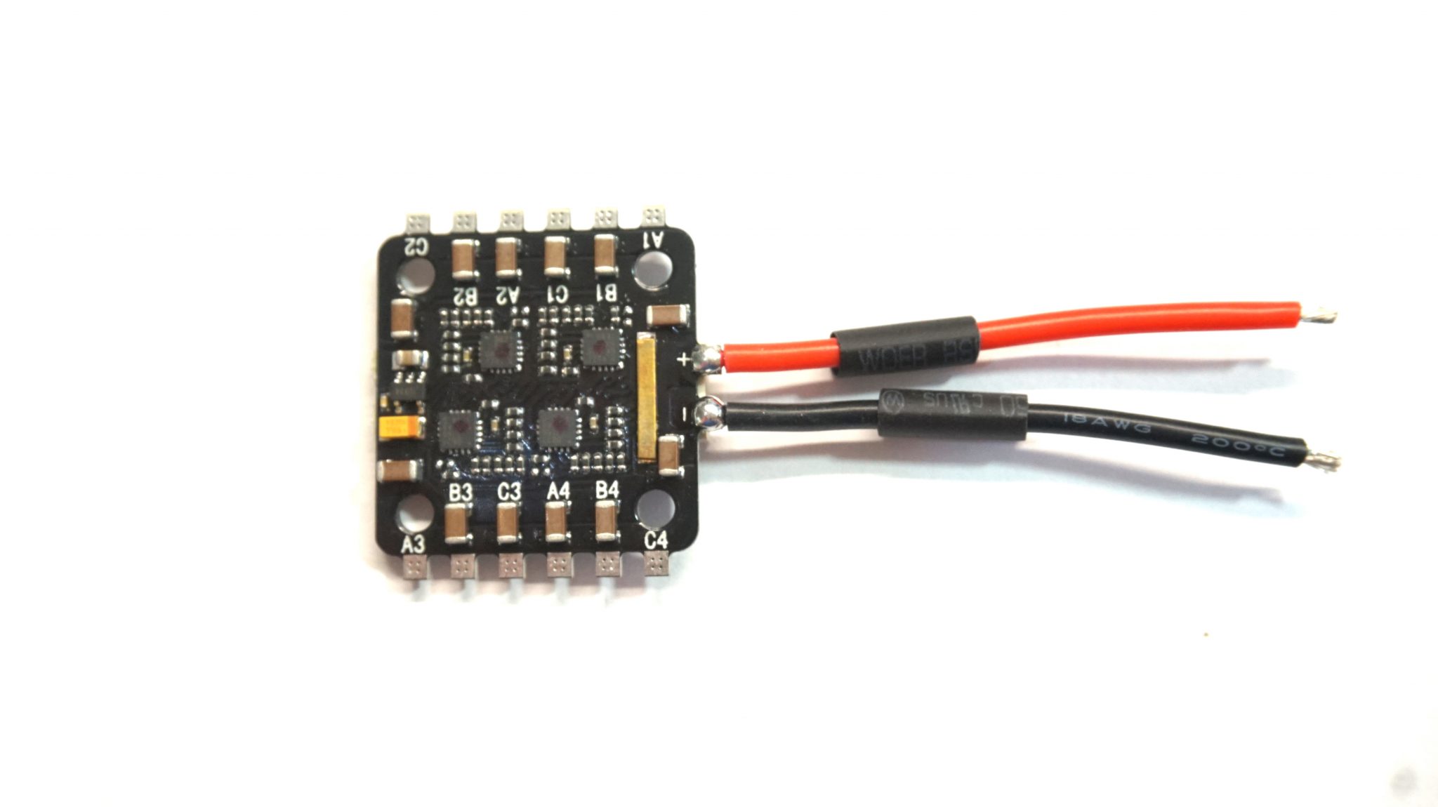
Step 2: Prepare and install the 4-in-1 ESC.
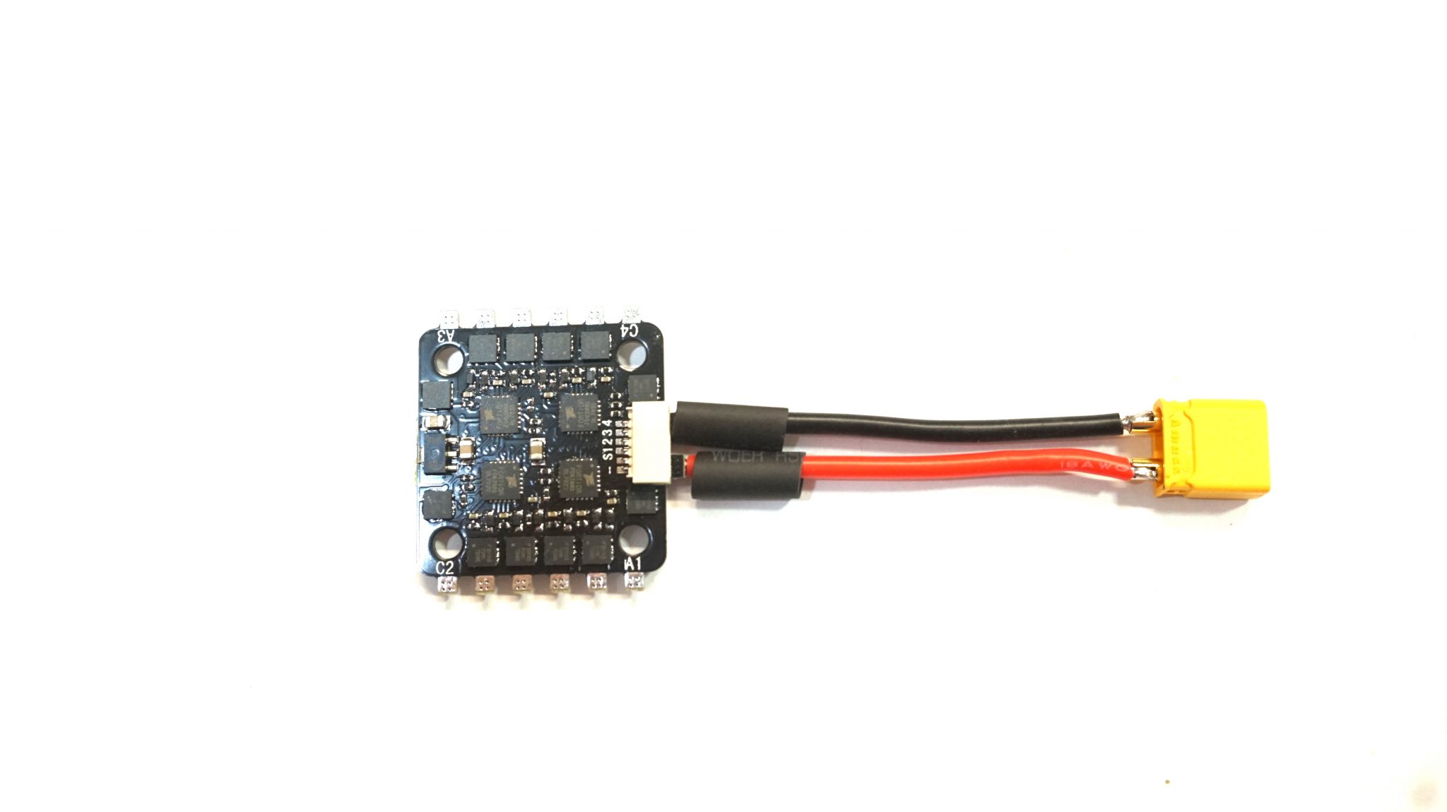
The Cicada 4-in-1 comes with battery leads pre-soldered but we need to install an XT30 battery connector to these leads. Slide the appropriate heat shrink over the bare wires but do not apply heat yet. Solder the XT30 to the appropriate leads.
Note that it’s always a good idea to plug a spare XT30 connector (not a battery, just the plug!) into the one being soldered. This will reduce the chance of warping or melting the XT30. Once the XT30 is installed and cool, slide the heat shrink over the copper connections and shrink in place.
You can now place the 4-in-1 ESC over the nylon screws. Place it face down so that the plastic servo connector plug is on the bottom. The nylon spacers on the center bolts will provide enough clearance so that the servo plug does not touch the frame.
Pre-tin the motor lead pads on the 4-in-1 ESC. Be careful not to touch the nylon center screws with your soldering iron as they easily melt.
Finally, locate the wiring harness that comes with the 4-in-1 ESC. The wiring harness consist of six wires connected to a JST plug. We will only be using the ESC wires (orange, blue, yellow, green) and will remove the positive and negative (red and black) wires. To remove the red and black wires, use the tip of a sharp knife to lift the small plastic tab above the connector of the corresponding wire. With the tab lifted, the entire wire and crimped end should slide out of the connector.
Plug the 4-wire harness into the ESC.
Step 3: Solder the motors and FC power leads
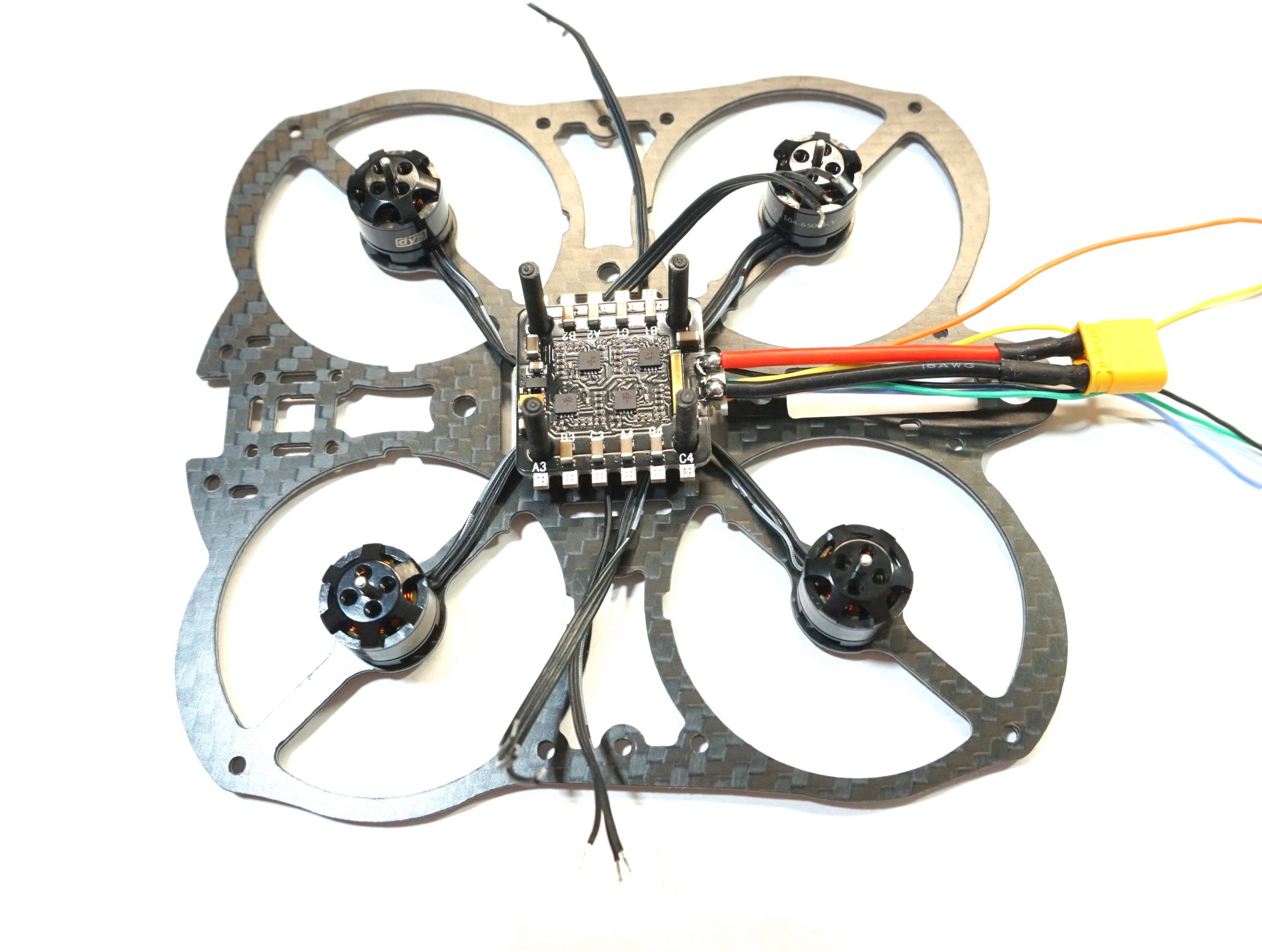
Carefully route the motor wires under the ESC so they wrap around the center screws and around the bottom of the ESC. This routing method will keep the motor wires nice and neat and will help avoid being snagged by a prop.. Confirm your measurements and trim each motor wire.
Strip ~2mm of insulation off each motor wire and pre-tin them. Take care not to pre-tin any wires directly over the ESC, as tiny drops of solder can land on the ESC and damage or short the mounted components.
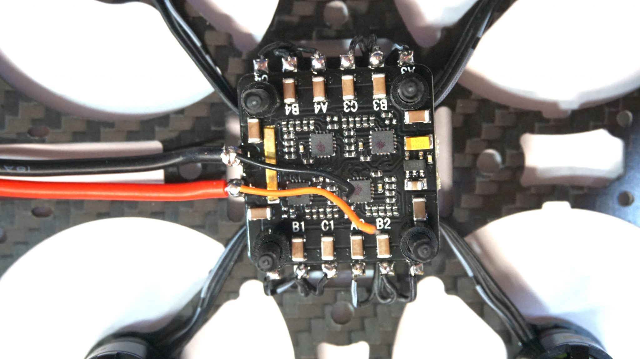
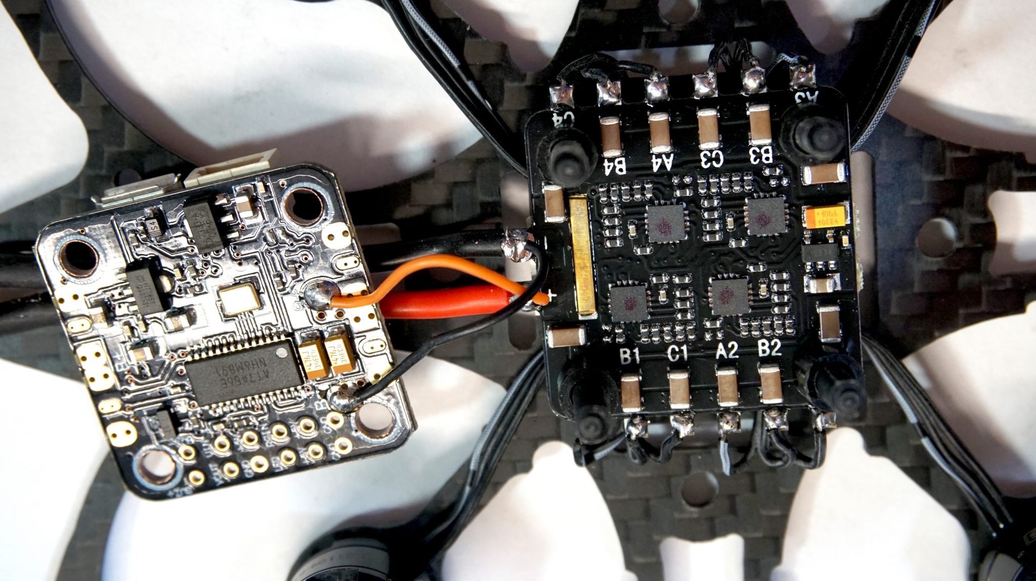
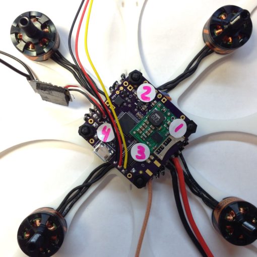
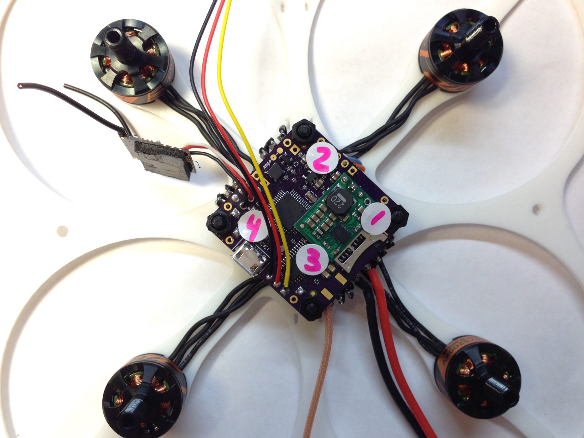
Once all the wires are pre-tinned, solder each wire to the appropriate pads on the ESC. Note that the motor layout and ESC pad orientation aren’t consistently named! Specifically, motor 3 will be soldered to pads A4, B4, and C4. Motor 4 will be soldered to pads A3, B3, and C3. Motors 1 and 2 solder to the properly numbered pads. Don’t worry about which individual motor wire goes to which pad in the group of three, as we will set motor spin directions in the BLHeli Suite software.
We will now attach power leads for the flight controller. Trim two pieces of 20-24 awg wire to about 30cm and strip and tin the ends. Solder one to the positive battery lead joint and one to the negative battery lead joint as shown in the photo. The orange wire is the positive and the black wire is ground. Leave the other ends loose for now.
Step 4: Connect power and ESC leads to the Flight Controller
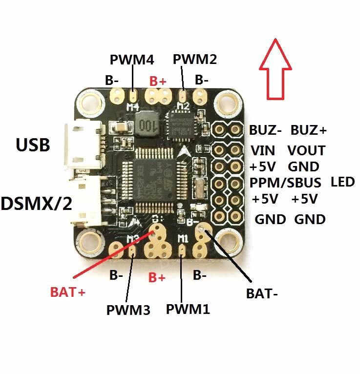
Identify the top and bottom of the Omnibus Mini F3 flight controller. The top is the side with the USB port and the directional arrow which indicates the front. Turn the flight controller over and solder the power leads that you soldered to the battery leads in Step 3 to the B+ and B- pads on the bottom of the flight controller. In our example, the positive lead is orange and should be soldered to the B+ pad. The black lead is ground and is soldered to the B- pad.
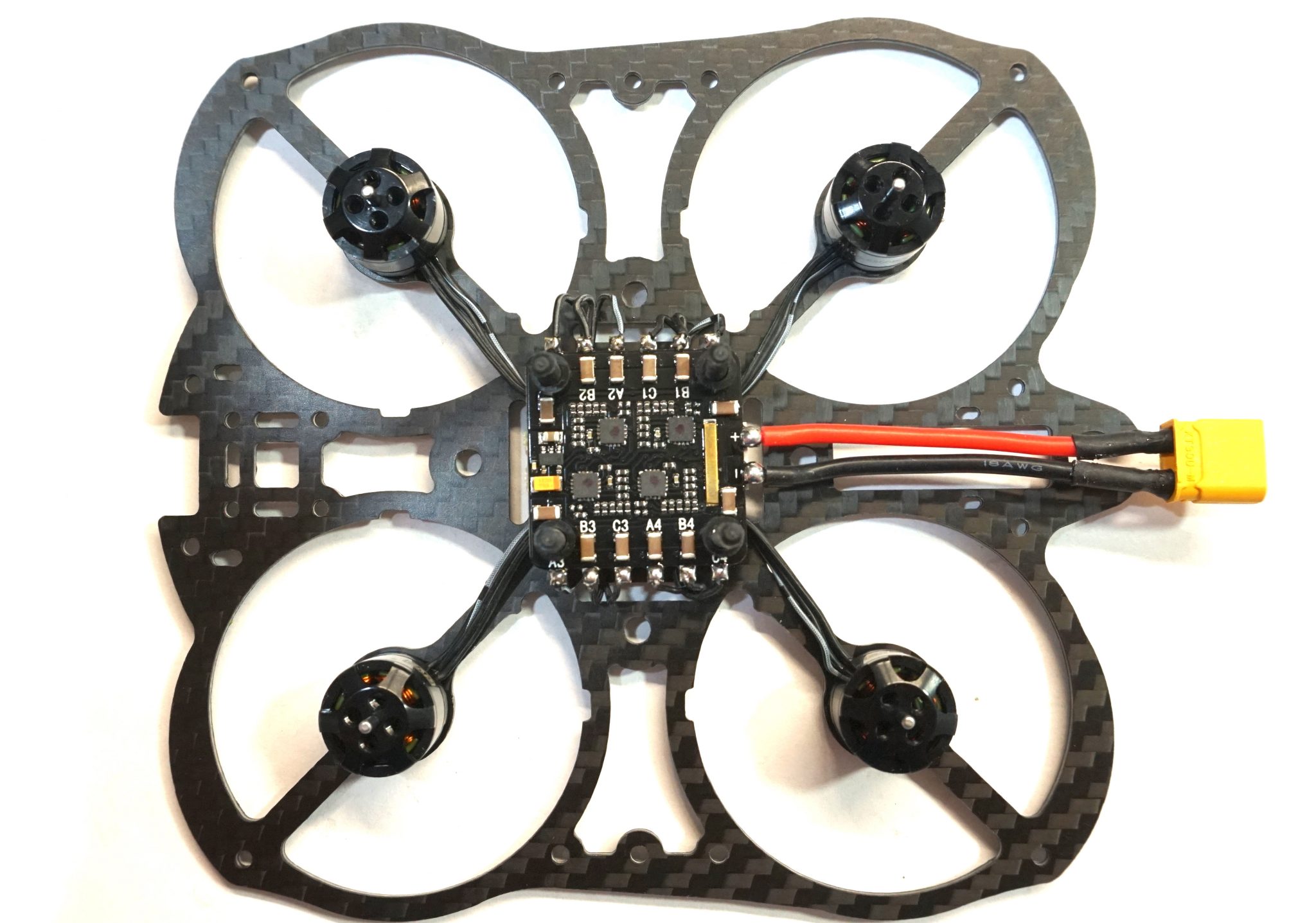
Install spacers on each of the four nylon center stack screws. Turn the flight controller over so that the bottom faces the ESC and mount it onto the nylon center stack screws. Ensure the white direction arrow on the flight controller faces the front of the frame.
Locate the servo leads coming from the ESC (orange, blue, yellow, green). If you connected the motors to the ESC pads as described in Step 3, the servo wires correspond to the motors as follows:
| Motor | Position | ESC Pads | Servo wire color |
| 1 | Right rear | A1, B1, C1 | Green |
| 2 | Right front | A2, B2, C2 | Yellow |
| 3 | Left rear | A4, B4, C4 | Orange |
| 4 | Left front | A3, B3, C3 | Blue |
Route the servo wires under the flight controller and around the edge to the appropriate pad. Measure and cut the wire (removing the single black servo connector). Strip about 2mm of insulation and tin the wires. Again, take care not to tin the wires directly over the flight controller as solder splatter can damage the components.
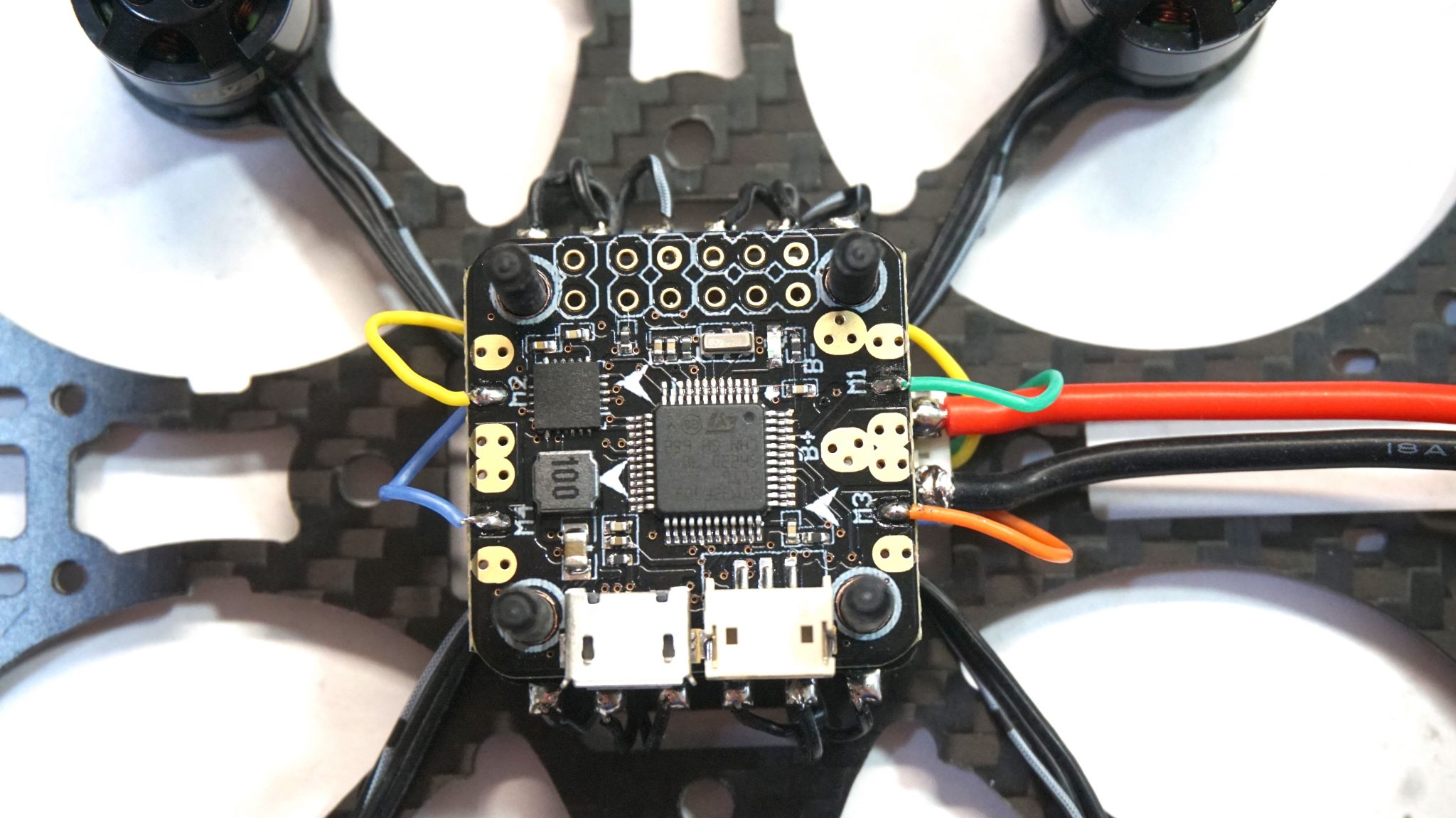
Solder each servo wire to the appropriate pad on the ESC. You can use a small dab of hot glue once the joint has cooled to add strength.
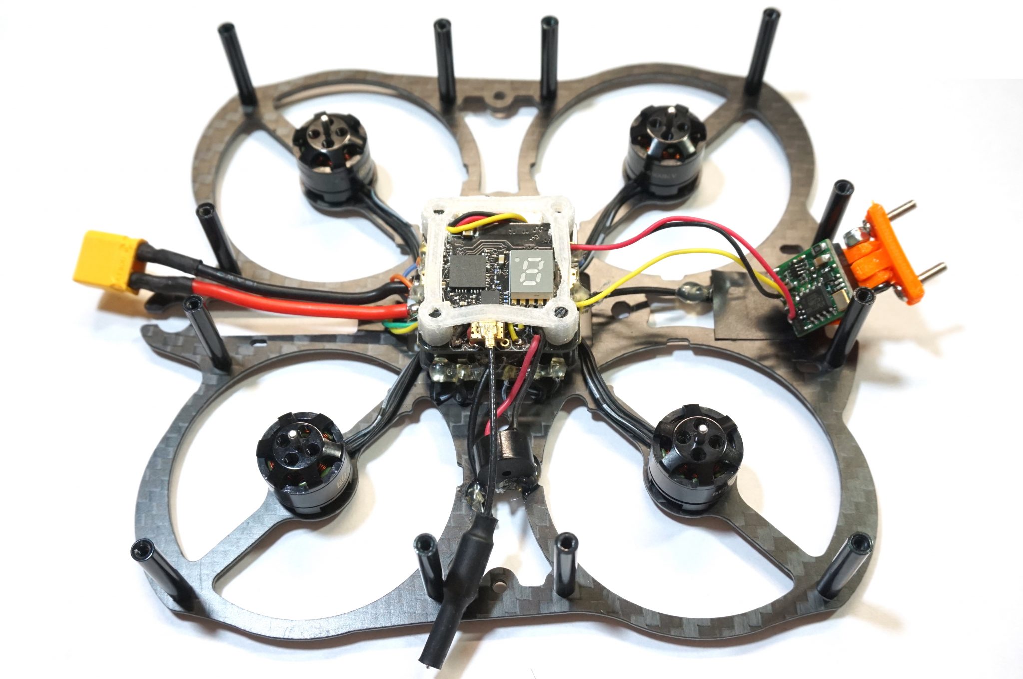
Step 5: Install the Pololu voltage regulator (optional)
Because there is a chance that the flight controller’s onboard BEC will not always provide enough power for the video transmitter, we are going to install a Pololu 5v voltage regulator in parallel with the flight controller’s 5v rail. This is usually not required when running 2s but can reduce the chance of video loss when running 3s.
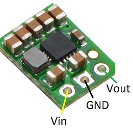
Use three small (20-24 awg) wires. In our model, we used yellow, black, and green. Identify the three pin holes on the Pololu. When looking at the front (the side with the components) and with the pin holes on the bottom, the pin holes are, from left to right, Vin, GND, and Vout. Tin each pin hole and strip and tin each wire. Solder the yellow wire to the Vin pin hole, GND to the middle pin hole, and green to the right pin hole.
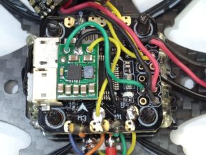
Next, tin the B+ pad, the B- pad, and the 5v+ pin hole on the flight controller. Solder the yellow Vin Wire to the B+ pad. Solder the black GND wire to the B- pad, and solder the green Vout wire to the 5v+ pin hole.
The Pololu regulator will now ensure steady power to the 5v rail on the flight controller that is powering the FPV system.
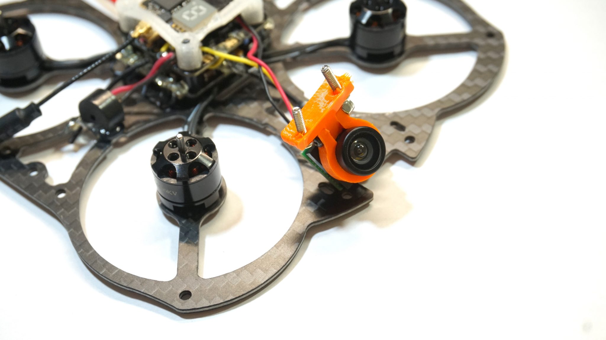
Step 6: Install the FPV gear
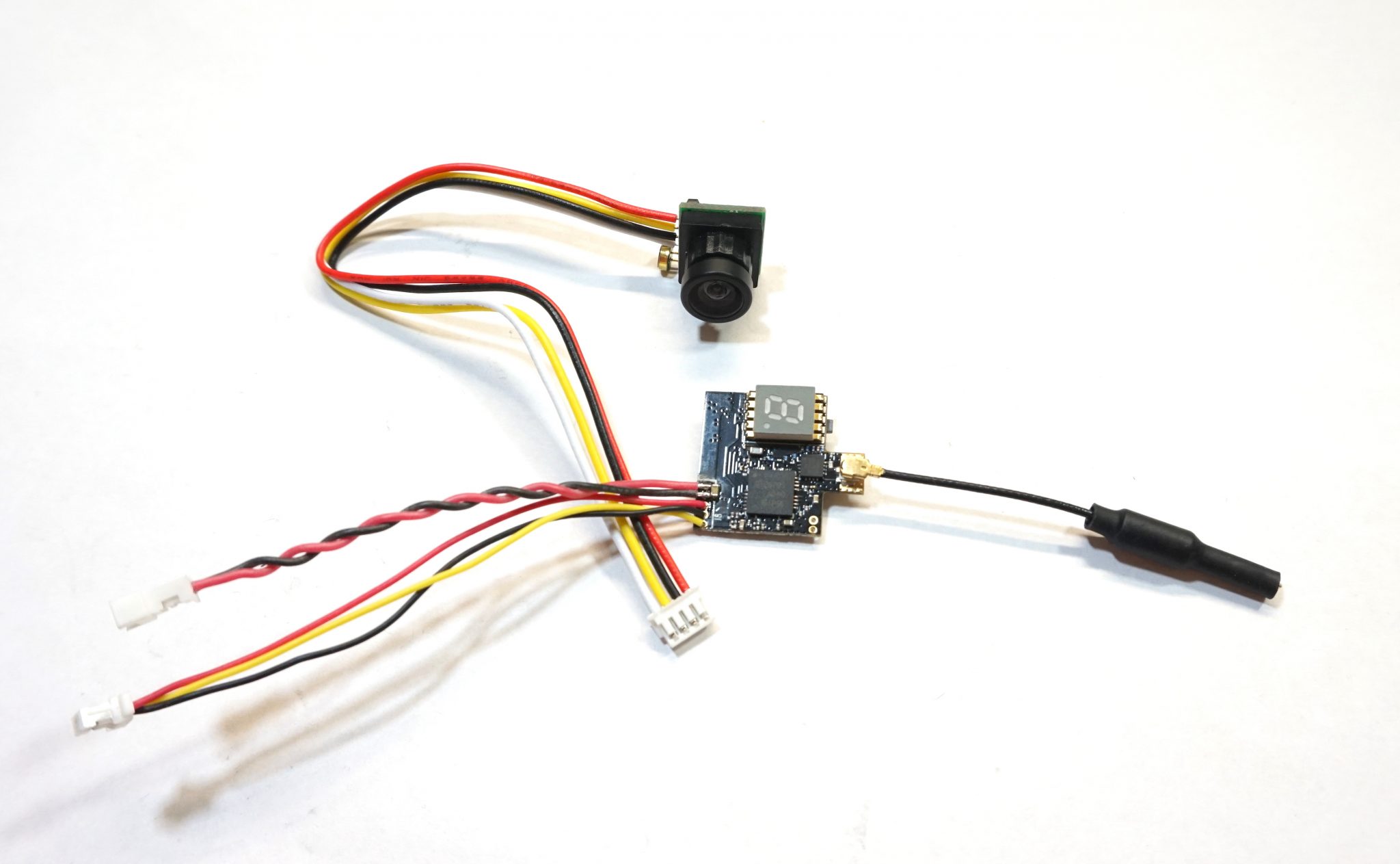
We will be using the Tiny FPV kit which consists of a Diatone 600TVL Camera and an Eachine ATX03 Super Mini 5.8G 72CH 25mW/50mw/200mW Switchable FPV Transmitter. We will be routing the video signal through the Omnibus Mini F3 flight controller to take advantage of its OSD capability.
Examine the back of the Diatone 600TVL camera and identify each of the leads. Desolder and remove the white (sound), red (voltage), and black (red) wires. The only wire that should remain is the yellow (video out) wire.
Examine the Eachine ATX03 video transmitter and identify the red and black pair of wires that terminate in a 2-pin connector and the set of red, black, and yellow wires that terminate in a 3-pin connector. The red and black pair is use to power the vtx and will be directly soldered to the flight controller. The red, black, and yellow set of wires are power and ground to the camera and video out of the camera to the video transmitter.
Cut the connector off the red, black, and yellow set of wires. Measure and cut the red and black wires to about 60mm and the yellow wire to about 40mm. Strip and tin the three wires. Solder the red wire from the vtx to the power pad on the camera. This is the pad on the camera you removed the red wire from earlier. Repeat for the black wire, soldering it to the pad that you removed the black wire from earlier.
If you’ve forgotten which pad on the camera is for which wire, refer to the photograph. When looking at the back of the camera, with the microphone on top, the red wire should be soldered to the left of the yellow wire and the black wire to the right of the yellow wire. The pad which previous held the white wire will not be used. The yellow wire in the middle should still be in place.
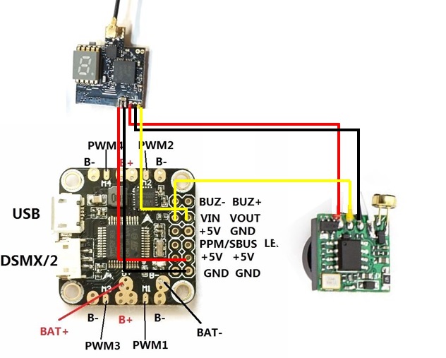
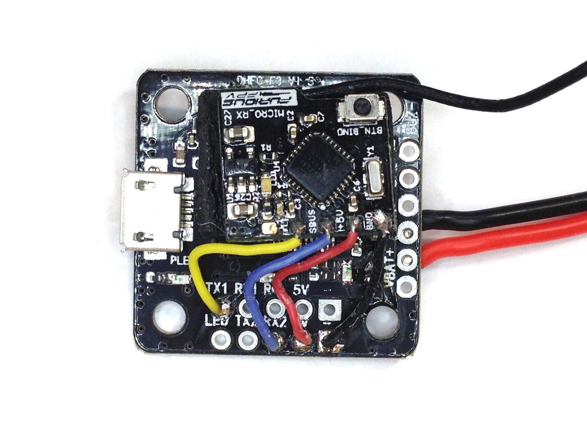
Next we will connect the video transmitter to the flight controller. Cut the connector off the red and black pair of wires, trim to length, and strip and tin the ends. Tin the +5v and GND pin holes on the flight controller’s pin rail and solder the red wire to the +5v pin hole and the black wire to the GND pin hole.
Finally, solder the yellow video out wire of the video transmitter to the Vout pin hole and the yellow video from the camera to the Vin pin hole.
The FPV system is now installed and will utilize the native OSD of the Omnibus Mini F3 flight controller.
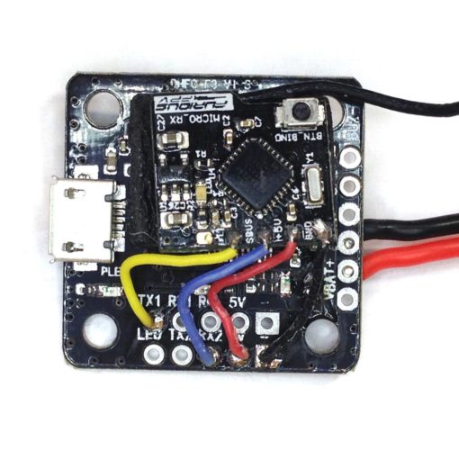
Step 7: Install the radio receiver and buzzer
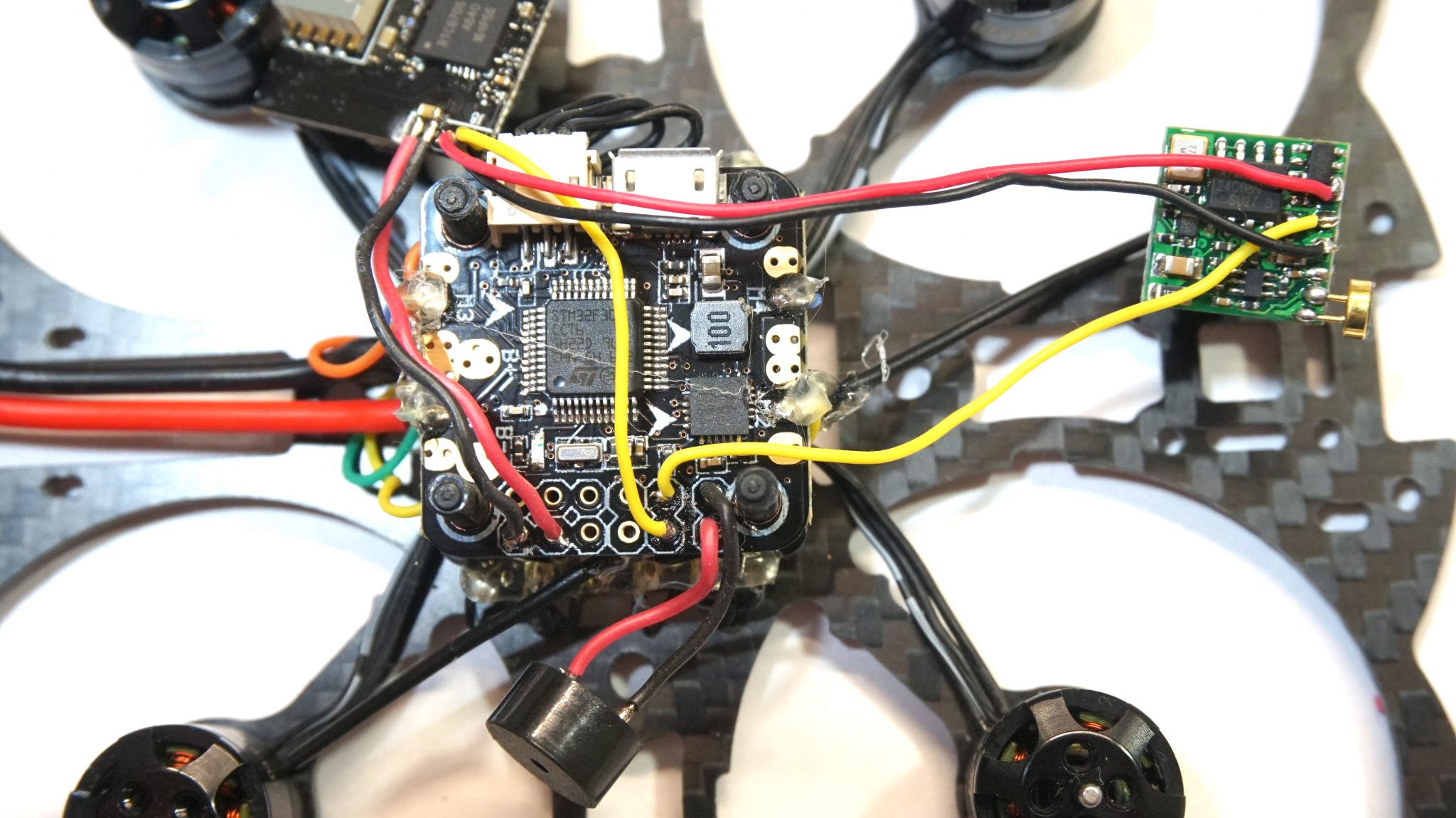
Because we are using a Lemon Rx DSMX Satellite Receiver, we can simply plug it into the Spektrum port on the flight controller. De-case the receiver and place it between the ESC and flight controller, ensuring the diversity antennae are clear of the prop path. Plug the connector into the Spektrum port on the flight controller.
If you are using a FrSky receiver, you will utilize the 5v, GND, and SBUS pin holes on the flight controller’s pin header.
To install the buzzer, solder two short lengths of thin gauge wire to the positive and negative terminals of the buzzer. Solder those wires to the BUZ- and BUZ+ pin holes on the flight controller.
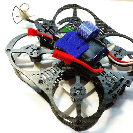
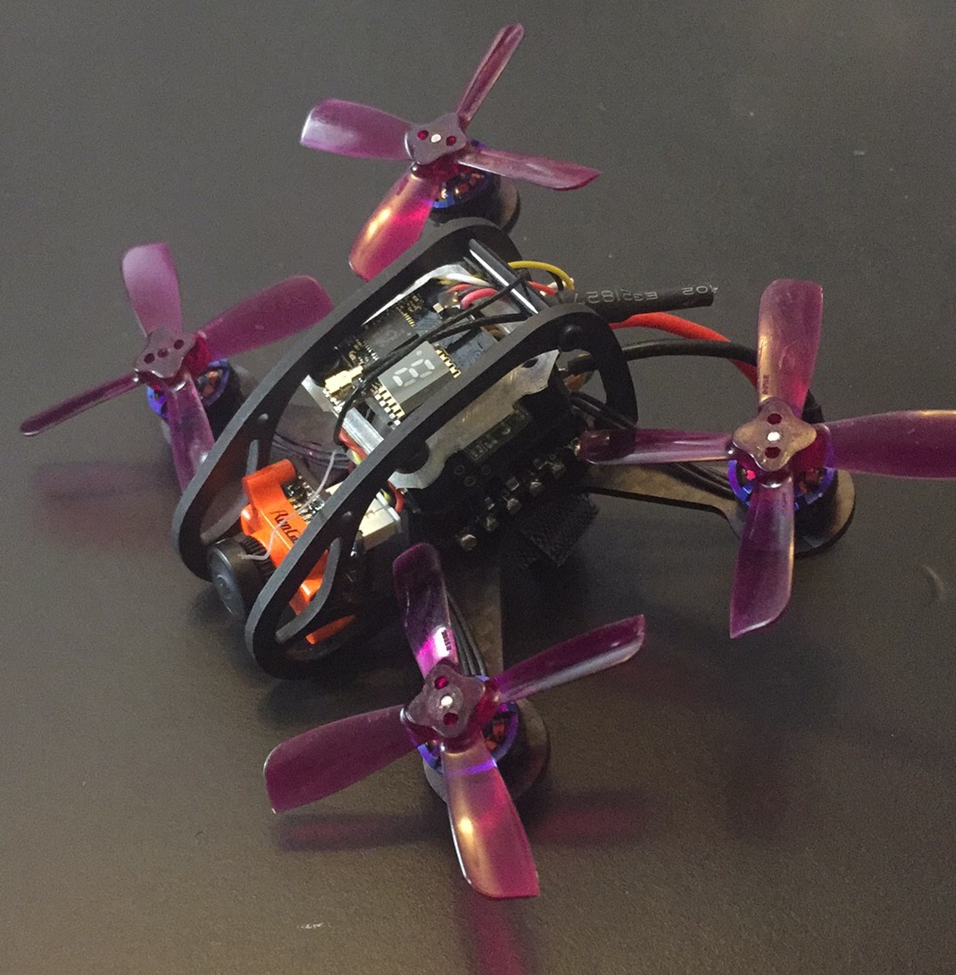
Step 8: Final assembly
Place the VTX on top of the flight controller stack and place the 3D Printed bracket over the nylon center stack screws. Turn the screws careful to thread them into the 3D printed bracket and tighten over the VTX. This will secure the entire center stack and also facilitate easy removal of the top plate.
Install the flexible mini camera adjustable mount ring around the camera lens body and secure to the mounting bracket. Install the mounting bracket onto the top frame plate so that the camera is suspended from above.
Install the 12, 20mm aluminum standoffs into the lower frame plate
Slip the battery strap into whichever slots you prefer to use to secure your battery. Install the top frame plate onto the standoffs.
Go back and install all motor screws, using blue Loc-tite for security. The Mini Owl Extreme is now ready for flight controller set up and the maiden flight!
