Click the Receiver tab in the left margin. This is where we will ensure the receiver is properly communicating with the flight controller and that your radio’s stick movements properly span the entire range of control. We will also configure two switches on the radio to communicate with the flight controller.
7a. Channel mapping
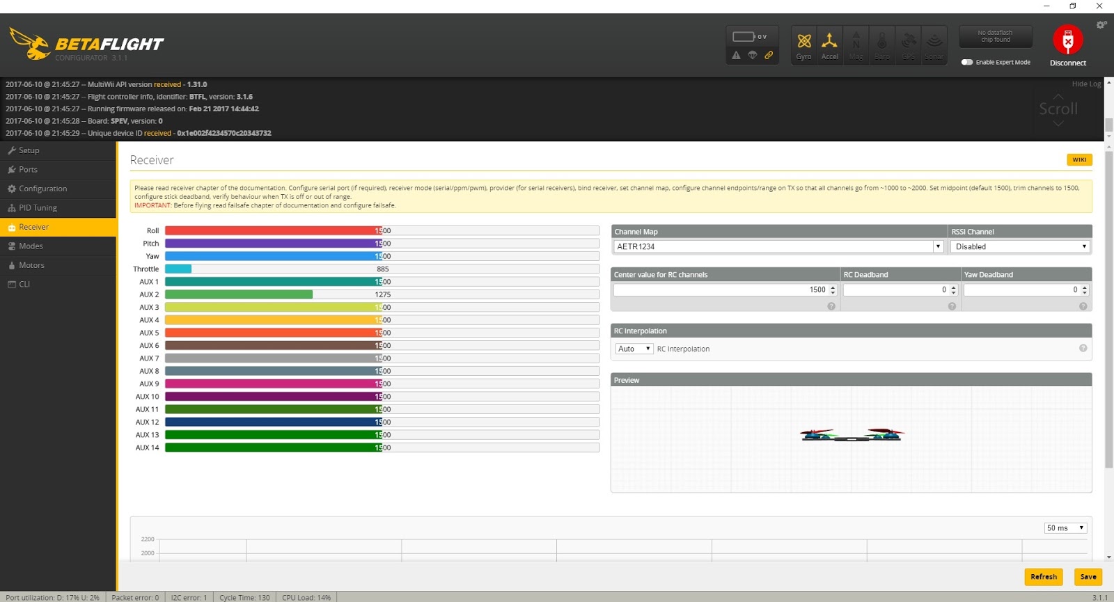
First, look on the right side of the Receiver tab to the channel map drop down. The channel map determines what stick or switch movements (a.k.a. inputs) on the radio are mapped to which communication channels on the flight controller. It may read something like AETR1234.
which means:
Channel 1 = Aileron (roll)
Channel 2 = Elevator (pitch)
Channel 3 = Throttle
Channel 4 = Rudder (yaw)
Channel 5 = Aux 1
Channel 6 = Aux 2
Channel 7 = Aux 3
Channel 8 = Aux 4
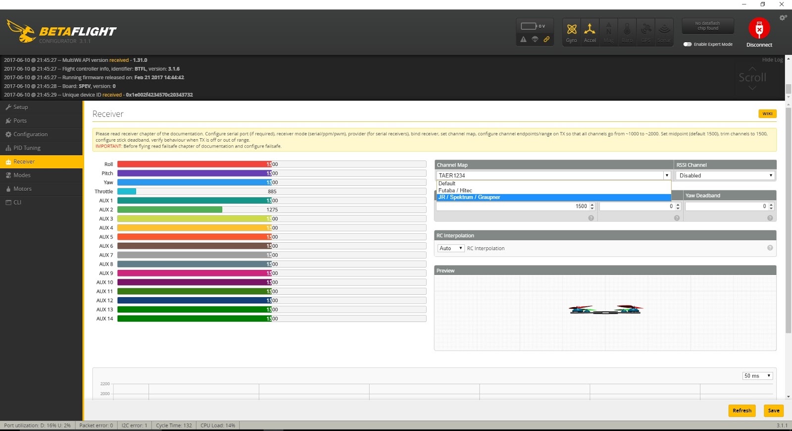
Unless you’ve changed your channel map on your Taranis, it uses TAER1234 channel mapping. To change this, simply click the drop down in the channel map section and select “JR/Spektrum/Graupner.” Alternatively, you can simply type “TAER1234” in the channel map box. The flight controller now knows which inputs to assign to which quad movements.
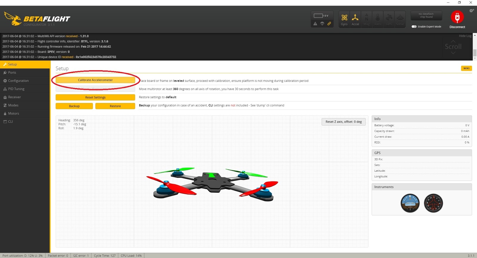
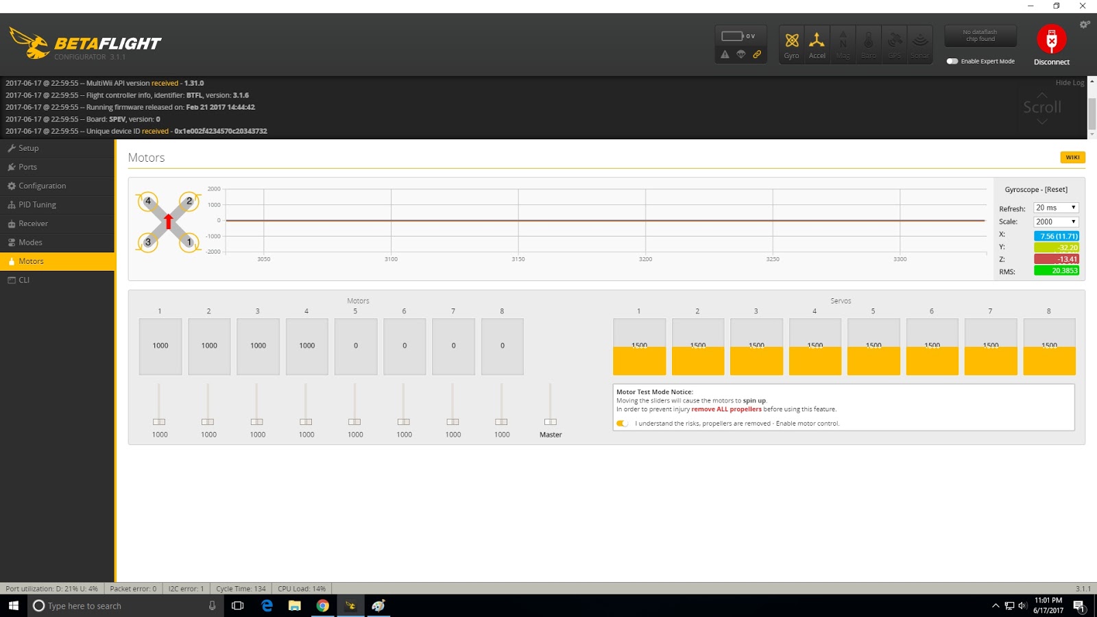
To test, you need to plug a battery into your quad as most receivers are not powered up via the USB port and need the battery to operate. REMOVE YOUR PROPS BEFORE PLUGGING IN A BATTERY! Turn on the radio, plug in a battery, and ensure the flight controller is still connected to the PC via a USB cable.
If the receiver is properly bound to the radio, stick movements should cause the colored bars on the left side of the Receiver tab window to move. If there is no movement in the bars, there could be several things wrong:
- The receiver may not be properly bound to the radio. Check the binding procedure for your specific receiver. A bound FrSky receiver usually displays a steady green light when bound.
- The quad is not plugged in to a battery. Many flight controllers do not power the receiver via the USB and require a Lipo to be plugged in.
- The receiver is not properly connected to the flight controller. Double check the connections and ensure the receiver is getting proper power from the controller and that the signal wire is connected to the correct UART Rx pin.
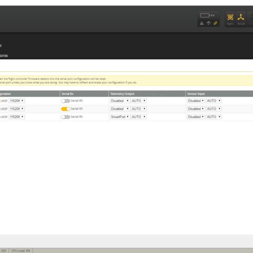
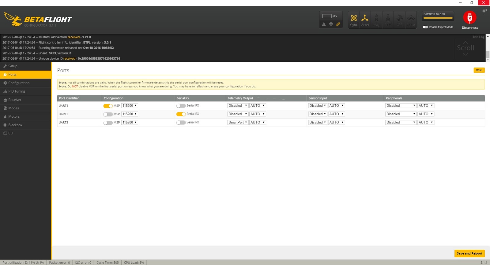
- The UART Port is not properly set up on the Ports tab. Revisit Step 5 of this guide and ensure the UART that the receiver is connected to is set as “Serial RX” on the Ports tab of the Betaflight configurator.
- The Serial Receiver Provider is not correct in the receiver section of the Configuration tab. Ensure Receiver Mode is set to “Serial-based receiver” and Serial Receiver Provider is set to “SBUS”.
- You are not using an SBUS receiver. If you are using an older receiver, it may communicate via PWM, PPM, or some other protocol. In that case, you will need to investigate the setup for that particular receiver.
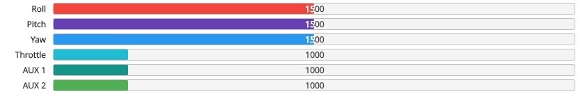
Move both sticks in all directions and ensure the colored bars move appropriately. The yaw, roll, and pitch bars should be very close to 1500 when the sticks are centered and should move from about 1000 to 2000 throughout the range. The throttle should be at 1000 when lowered and 2000 when raised to the maximum.
We will adjust these settings on the radio to get them exactly to those numbers later. For now, just ensure the bars are moving correctly with the appropriate stick movement. If they are moving but not mapped to the appropriate channel (for example, moving the throttle causes the Roll bar to move), then recheck the channel map as above. Again, unless something has changed on the Taranis, the channel map should be TAER1234.
7b. Switch mapping
With the stick movements properly mapped, it’s time to map the switches. Unlike sticks, which are mapped for us when we selected TAER1234, we need to select which switches on the Taranis, of the many we can choose from, we are going to use. This is a bit confusing because it’s two separate steps: first we tell the radio which switches will communicate on which channel and then we must tell the flight controller (in a separate step) what those switches should do.
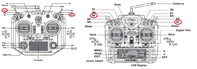
For our bare-bones setup, we’re only going to use two switches: An arm switch and flight mode switch. We will use a two-position switch for Arm/Disarm and a three-position switch for Flight Mode selection. You can use any switch that’s convenient for you as long as they have the right number of positions. But for this example, we will use Switch F (on the left side of the radio) as our two-position switch for arm/disarm and Switch D (on the right side of the radio) as our three-position switch for Flight Modes.
NOTE: Both the Taranis X9D and the Taranis QX7 use the same names and locations for the switches we are using so this guide applies to both radios.
Remember, your first four channels are already taken by the Throttle, Aileron, Elevator, and Rudder sticks. So we’re going to assign Switch F (for Arm/Disarm) to Aux 1 via Channel 5 and Switch D (for Flight Mode selection) to Aux 2 via Channel 6. We could assign two more switches to Aux 3 and Aux 4 but we don’t need those for our bare-bones setup.
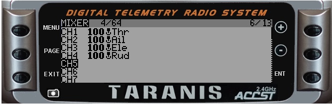
On the Taranis, navigate to the Mixer page (page 6/13) . You should see Channels 1 through 4 already assigned to your sticks so navigate down to channel 5 and long press the ENTER button.
Select Edit to start editing Channel 5. Navigate to the Source option and press the ENTER button. Once the cursor is flashing, indicating you are editing the source, simply flip Switch F and it will be appear as “SF” in the Source.
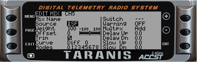
Exit out of that channel.
Repeat for Channel 6 and Switch D. Navigate down to channel 6 and long press the ENTER button. Select Edit to start editing Channel 6.
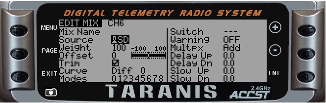
Navigate to the Source option and press the ENTER button. Once the cursor is flashing, indicating you are editing the source, flip Switch D and it will be appear as “SD” in the Source. Exit out of the channel.
Your switches F and D are now assigned to Channels 5 and 6, respectively.
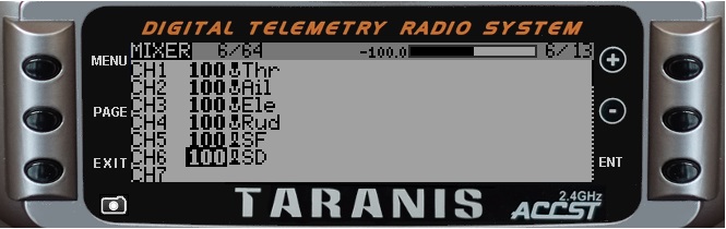
Exit out the mixer page and we will test the switch channels in Betaflight.
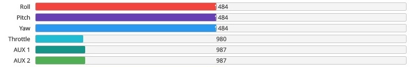
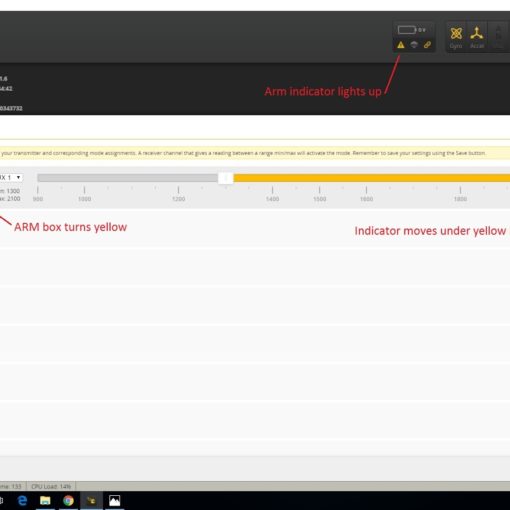
Go back to the Betaflight configurator Receiver tab to test your switch inputs. While watching the colored bar for Aux 1, flip Switch D through its three positions. The bar should move from about 1000 in the low position (away from you), should be about 1500 in the middle position, and should be at about 2000 in the high (towards you) position. Again, we will adjust these to be exact later.
Test Switch F in a similar manner. Because Switch F is a two-position switch, it should be at 1000 in the low position and 2000 in the high position.
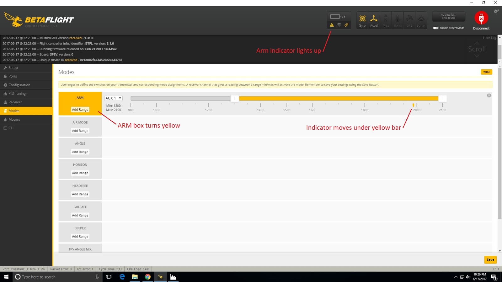
If the switches aren’t responding correctly, go back to the Mixer page of the Taranis and ensure the correct switches are assigned to the correct channels. Note that, currently, the switches don’t actually do anything other than transmit their position to the flight controller. Assigning them to arm the quad and change flight modes is done in Step 8.
7c. Center point and end point calibration
The last thing to do on the Receiver tab is to ensure the endpoints and center points are correct. Specifically, it is critical that the flight controller sees 1000 when a stick as at the low point (bottom or left, depending on the stick) and 2000 when it is at the high point (top or right, depending on the stick). It is also critical that the pitch, roll, and yaw sticks read 1500 when centered. The throttle stick doesn’t self-center so the center point isn’t critical.
Without properly set end points and center points, the quadcopter will be difficult to control, may not be able arm, and will drift annoyingly when the sticks are centered. Setting end points and center points can be tedious but it’s fairly easy.
Again, REMOVE YOUR PROPS BEFORE PLUGGING IN A BATTERY! Turn your Taranis on and plug in a battery. Click the Receiver tab on the Betaflight configurator and observe the colored bars.
We will adjust the Roll center point and end points first. Without touching the sticks note the reading on the Betaflight configurator Roll bar. If it is not exactly 1500 we will need to adjust it. If it is exactly 1500, you can move on to adjusting the end points. Navigate the Taranis menu to the Outputs page (page 7/13). You will see all your channels represented and several columns of data that can be adjusted. The first column, which probably reads “100” is to adjust the low point (MIN) of the stick. The second column, which probably reads “100” is to adjust the high point (MAX) of the stick. The third column, which probably reads “1500” is to adjust the mid-point (PPM Center) of the stick. Press the ENTER button on the Taranis and then use the “-” key to navigate to the mid-point adjustment setting. Press ENTER again to begin editing and the “1500” will flash.
Mid-point adjustment for Channel 1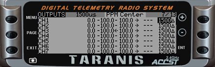
While watching the colored bar on the Betaflight configurator for Roll, use the + and – keys on the Taranis to change the mid-point value until the bar on the configurator reads 1500 exactly. When complete, press the enter button to exit editing mode.
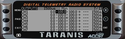
Next we will adjust the low point. Navigate to the low point reading for the Roll channel and press ENTER to begin editing. Push the roll stick all the way left and note the value in the colored bar on the Betaflight configurator. If it doesn’t read 1000, use the + and – keys on the Taranis to adjust the low point until it reads exactly 1000 on the configurator.
Low point adjustment for Channel 1
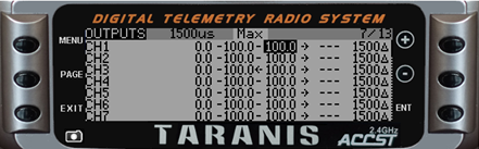
Repeat for the high point setting. Then repeat for Pitch, Yaw, and Throttle, noting that there is no need to adjust the mid-point for throttle since it does not automatically center.
High point adjustment for Channel 1
You can adjust the end points for the arm switch (Switch F) and the end points as well as the mid point for the Flight Mode switch (Switch D) similarly if you desire.