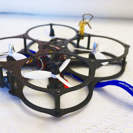
Designed for acro and FPV Micro and Mini racing indoor with SUB-130 size, this board provides the most-needed features in a compact and practical form factor, on a 27x27mm board compatible with 20mm mounting hole spacing. Board include PDB support to hexa, built-in LC filter for FPV video signal. The board is supported with Cleanflight and Betaflight firmware and uses the more-powerful STM32F3 microcontroller, with 256K bytes of flash memory, 3 hardware serial ports plus USB, and a floating point math coprocessor for fast control looptimes.
The board provides stable voltage regulation with the option for a directly connect lipo up to 5S operation, high-current buzzer on 5V, SAT SBUS or PPM receiver connections, serial LED interface, low-pass filtered VBAT monitoring.
Features
- 27x27mm board with 20mm mounting M3 holes.
- 2.6g with high-quality gold plated 4-layer printed circuit board.
- Next-generation STM32 F3 processor with hardware floating point unit for efficient flight calculations and faster ARM-Cortex M4 core.
- Onboard regulator (BEC) 5V-2A for powering the FC, receiver and servos, camera. Direct connection to lipos up to 5S.
- PDB build-in support to Hex for SUB-130 size for very clean and easy to to setup. (For size > 130 required PDB external).
- LC filter build-in for FPV camera.
- Low-noise MPU-6000 SPI-bus gyro chip for faster acquisition of gyro data.
- Pass-through ESC-BLHELI programming and config with UART1.
- Battery monitor for voltage.
- Supports direct connection of SBus, SumH, SumD, Spektrum1024/2048, XBus receivers. No external inverters required (built-in).
- Dedicated SAT receiver interface with 3.3v using JST connector for compatibility with Spektrum/LemonRC cables
- Dedicated PPM receiver input with 5V power.
- 3 Serial Ports UART1, UART2, UART3 – NOT shared with the USB port.
- Micro USB port.
- Telemetry support.
- LED strip support.
- Buzzer port for audible warnings and notifications.
- Flashing via USB or serial port.
- Use all the features all the time. Connect your USB + OSD + SmartPort + SBus + GPS + LED Strip + Battery Monitoring + Sonar + 6 motors – all at the same time.
- Reverse current protection on lipo and USB inputs for problem-free ESC calibration.
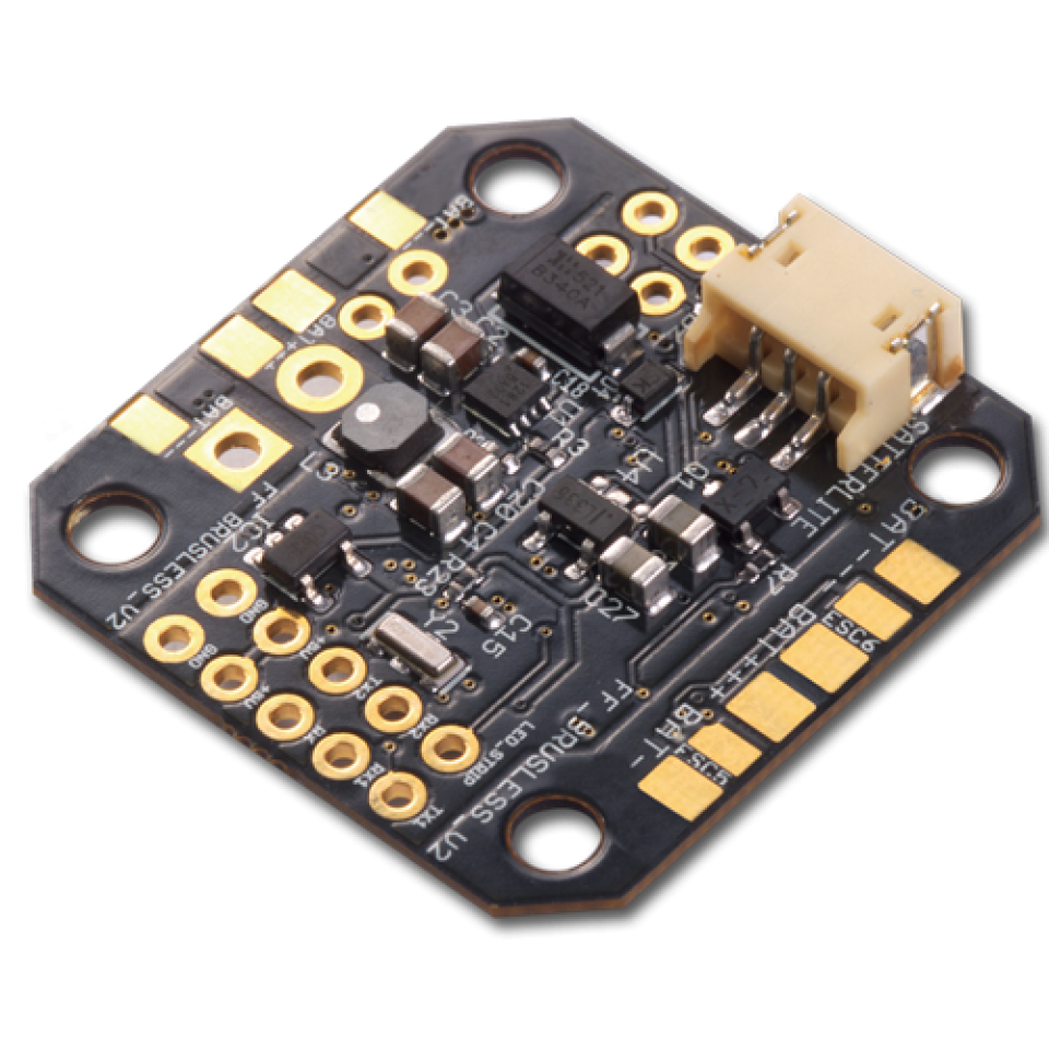
Board Pinout
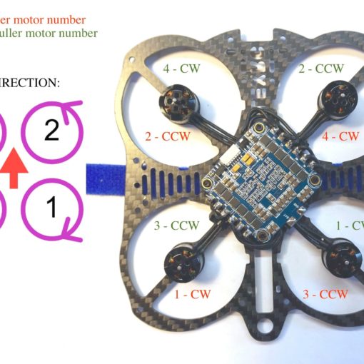
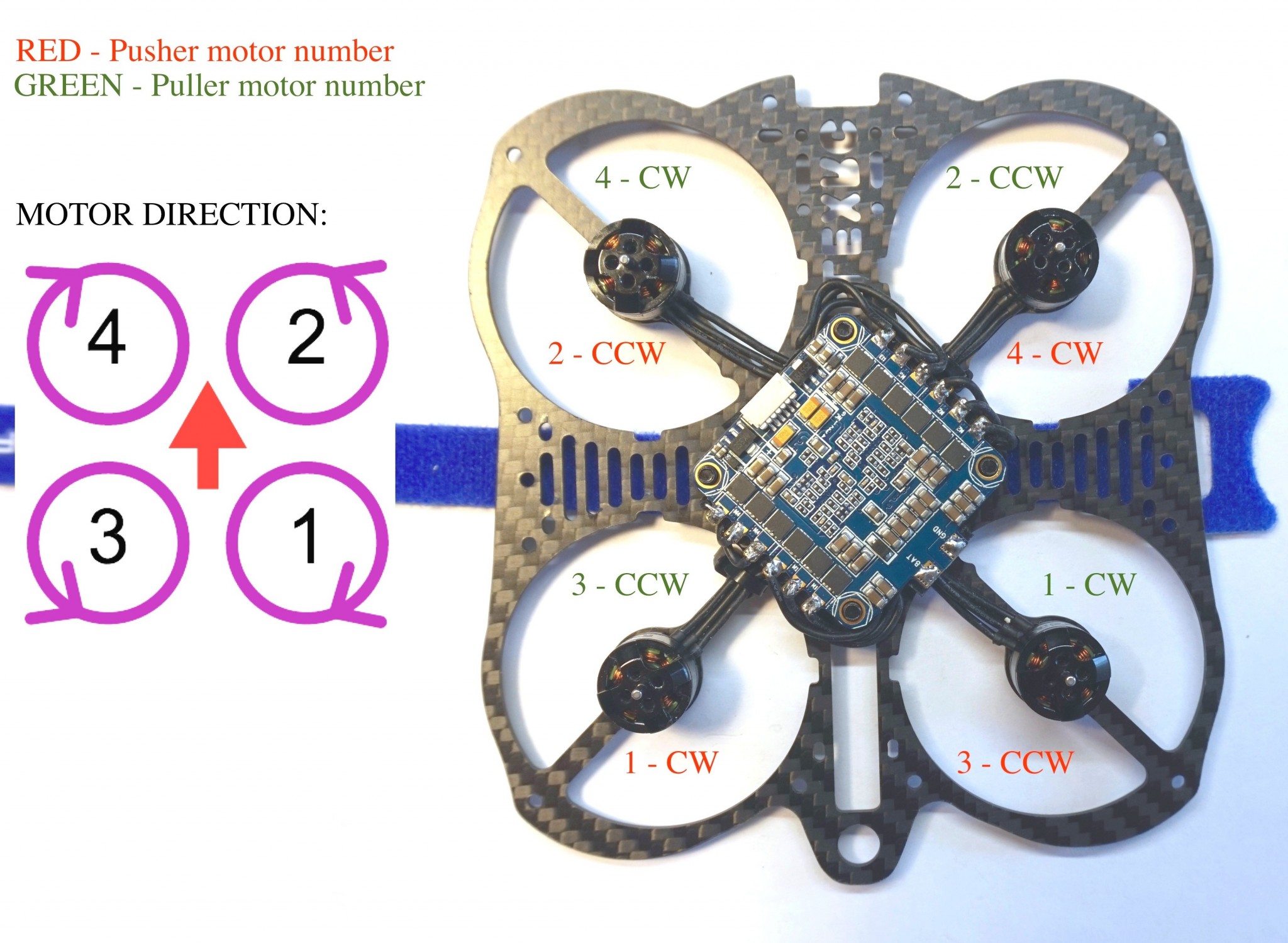
On the board the ESC ports are labeled on the silk screen layer as ESC1 to ESC6.
Pads are provided for PWM signal, and BAT + and BAT — are either side when using internal power distribution. These pads can be left open if an external power distribution board is used. The diagram below shows the position of the boot pins. It may be necessary to short those to activate the bootloader. BAT and GND are for connecting a flight battery directly using the internal switching regulator.
The board is compatible with up to a 5s LiPo directly connected.
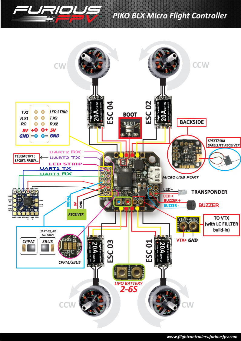
Connection / wiring diagram
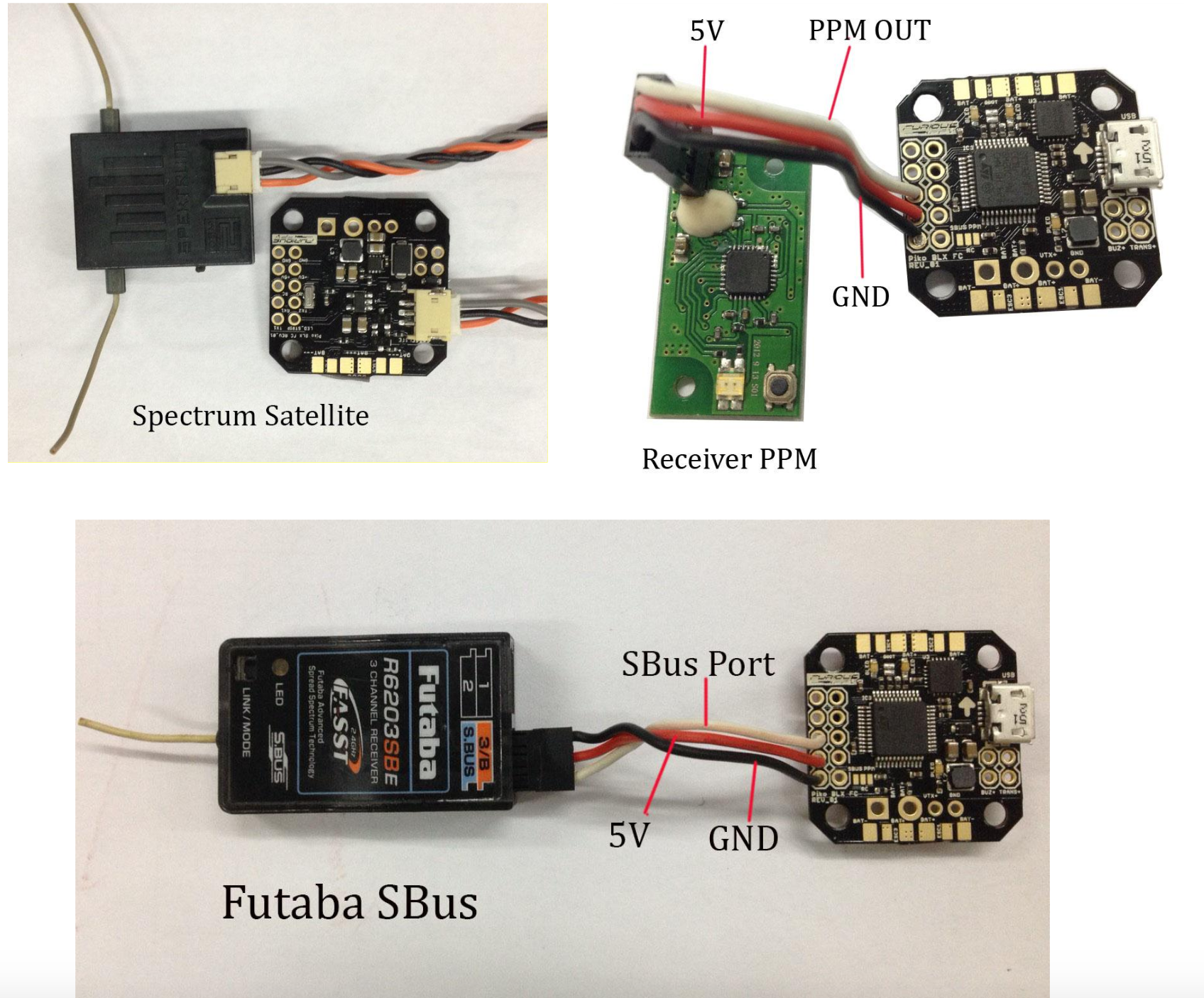
Receiver connection
Spektrum RX: The onboard JST connector is connected to a 3.3V voltage regulator and using UART3.
SBUS: Solder the jumper to SBUS and connect your receiver to the PPM pin on the left side and using UART3.
PPM: Solder the jumper to PPM and use the PPM pin on the left side.
Quick start guide
Cleanflight / Betaflight configuration
1. Download latest firmware from:
- Raceflight: https://github.com/NightHawk32/raceflight/tree/PikoBLX_target
- Cleanflight: https://github.com/NightHawk32/cleanflight/tree/PikoBLX_target_cf
Betaflight: https://github.com/NightHawk32/cleanflight/tree/PikoBLX_target_bf
2. Install latest STM32 Virtual COM Port Driver http://www.st.com/web/en/catalog/tools/PF257938
3. Install and launch the Cleanflight Configurator tool https://chrome.google.com/webstore/detail/cleanflight-configurator/enacoimjcgeinfnnnpajinjgmkahmfgb
4. Connect flight controller to computer via USB cable.
5. Select the correct COM port, if it is not automatically detected.
6. Click connect, verify that communication is established. (Fig 1)
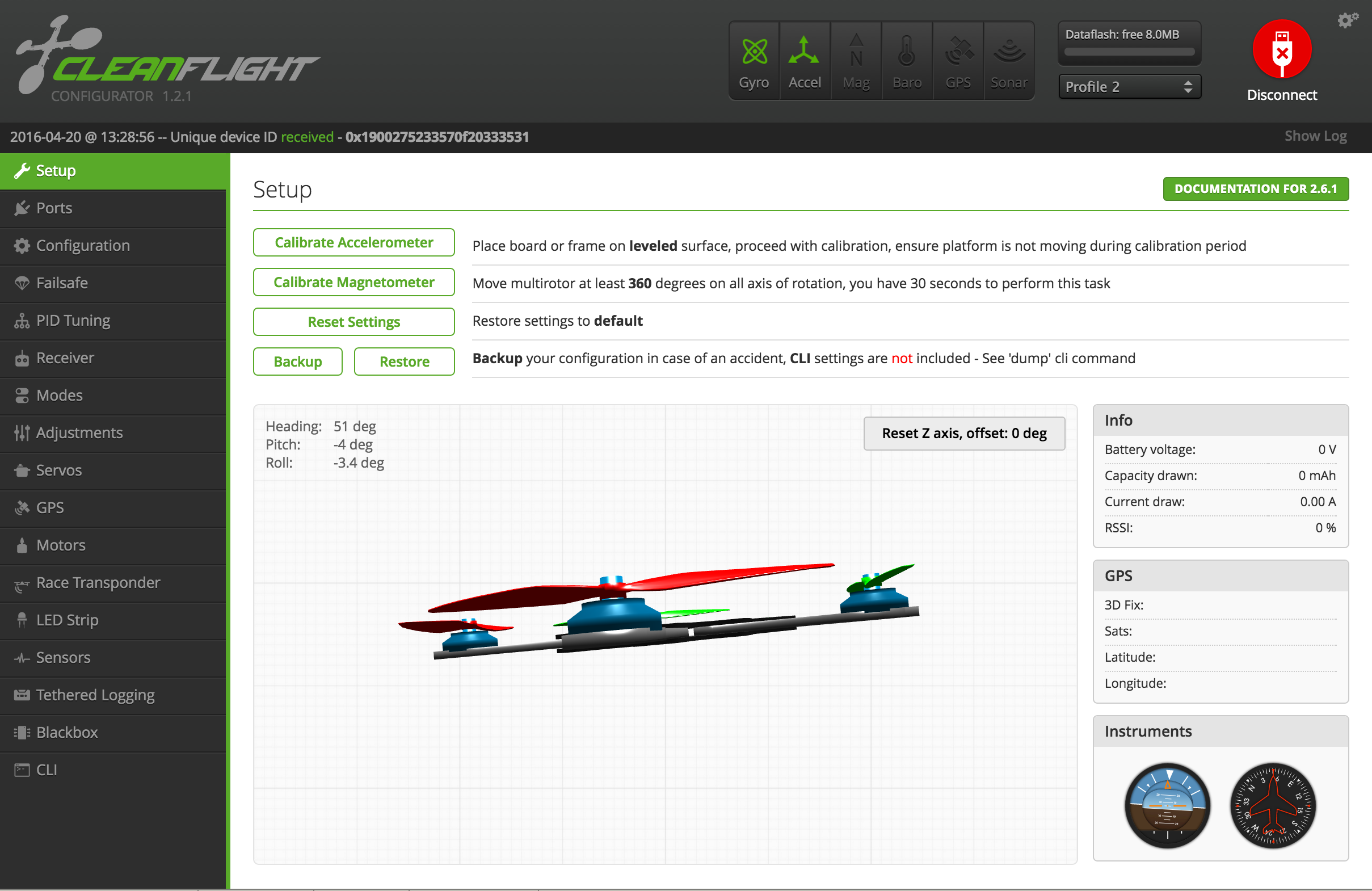
[Figure 1 – Setup tab after connection established]
7. Verify all sensors on your board are giving correct readings.
Serial ports configuration
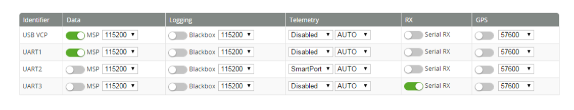
1. UART3 using for Serial receiver: SBus, SumH, SumD, Spektrum1024/2048, XBus.
2. UART2 using for Telemetry: Smartport…
- Cleanflight and Betaflight can send Smartport telemetry to the FrSky X-series receivers over a single wire. Connect UART2_TX port to the S.PORT pin on the receiver. It only takes one wire because the ground connection is already made with the SBUS cable.
- The voltage divider for lipo monitoring is built into the Furious FC. To enable lipo monitoring over Smartport: Enable VBAT and Telemetry on the Config tab Select Telemetry -> SmartPort and AUTO on the ports tab Set telemetry_inversion=on in CLI (This is the default in later firmware)
- The lipo voltage shows up in OpenTX as VFAS. The most useful telemetry parameters for me seem to be VFAS, RSSI, and RxBt (receiver input voltage).
3. UART1 using for OSD.
Receiver configuration
1. Receiver on Furious FC using UART3 for Serial receiver.
2. PPM and Sbus connect direction to RX port on Piko BLX FC board.
3. SAT receiver interface with 3.3v using JST connector
- Connect direct SAT receiver to JST connector on the bottom Furious FC board.
- Config RX_SERIAL on Configuration tab on Cleanflight software
- Serial Receiver Provider: SPECKTRUM1024 for 10bit or SPECKTRUM2048 for 11bit verison
4. Choose model/mixer (default is Quad X)
5. Configure receiver, set channel mapping
6. Configure channel mid and endpoints (1000-2000) and trim channels on transmitter
7. Ensure ESC calibration matches ESC configuration, recalibrate ESCs if needed
8. Learn about flight modes and configure channels/switches to activate them as required.
9. Learn how to arm/disarm
10. Bench-test failsafe
11. Read safety notes
12. First flight should be in Acro/Rate mode (the default mode when no other modes are active).
13. Tune PIDs and flight.
Most up to date manual can be found here
Also detailed instructions about Cleanflight configuration are available.
You can buy Piko BLX here
