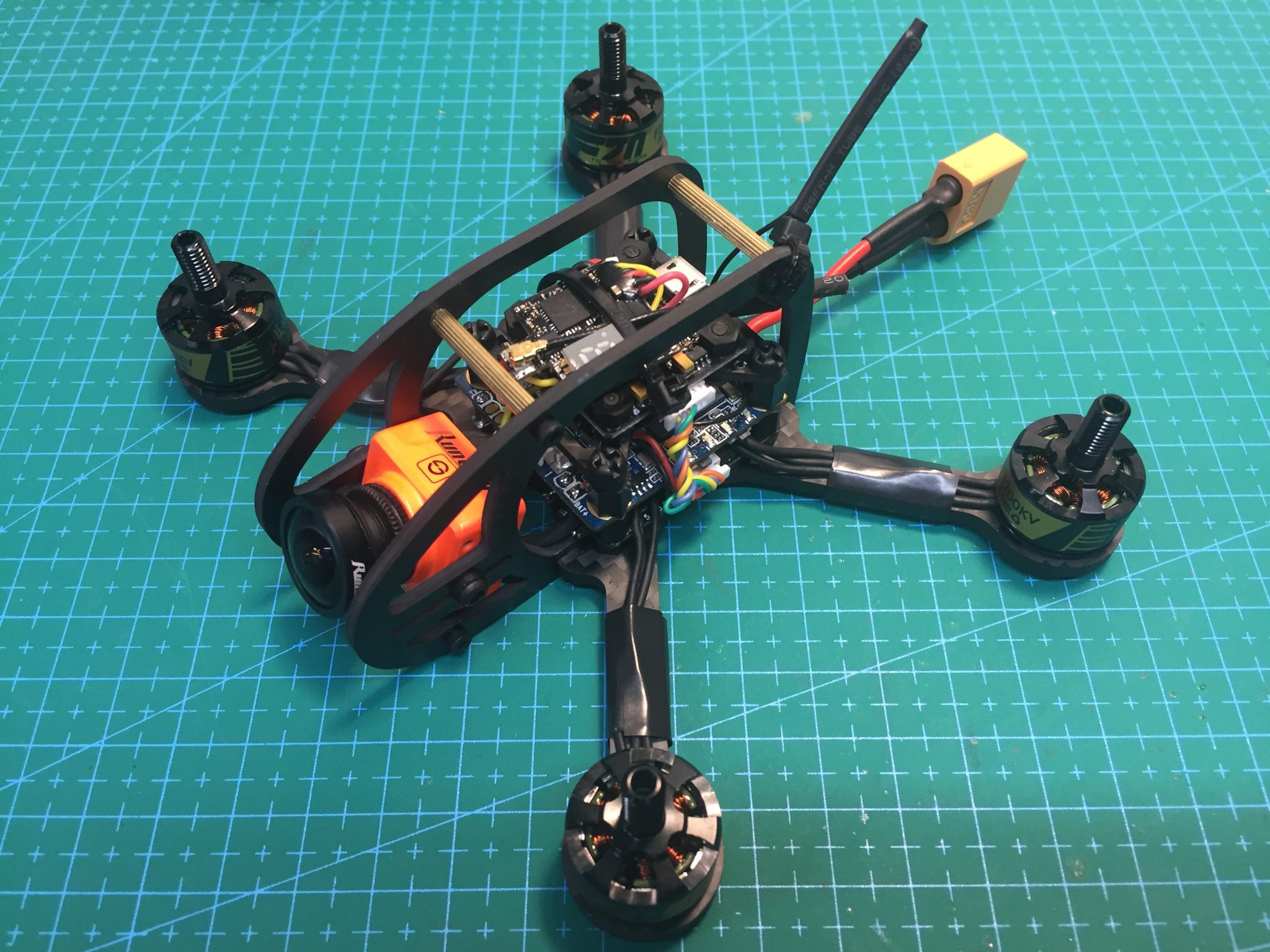
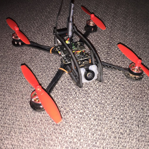
This guide will walk you through the assembly and setup of the FlexRC Ascent 3” The Ascent 3” builds upon the extreme success of the original Ascent, an innovative 2” quad with an integrated, no-hardware roll cage and fantastic flying characteristics. The single bottom plate is 3mm thick and with a Wide-X motor layout similar to an ImpulseRC Alien or QAV210. The roll cage serves to protect the electrical components and support the FPV camera.
This build is fairly easy for two main reasons. First, the frame design allows plenty of room for micro- or full-size components and standard nylon mounting hardware. Second, the roll cage installs to the base plate with no hardware. The entire frame consists of just three pieces and that includes the camera mount.
The only non-standard portion of this build is how we power the electrical components due to the fact that the Runcam Split board requires 5v and relatively high amps. This will be covered in detail below.
Components
Frame: https://flexrc.com/product/ascent-3-frame/
Motors: https://flexrc.com/product/t-motor-f20-1406-3200kv-4pcs/
Flight controller: https://flexrc.com/product/mini-f3-flight-controller-with-osd/
ESCs: https://flexrc.com/product/fx20a-v2-4-in-1-20a-cicada-busybee2-esc/
FPV Camera: https://flexrc.com/product/runcam-split/
Video Transmitter: https://flexrc.com/product/eachine-atx03-fpv-transmitter/
Receiver: https://flexrc.com/product/frsky-xm-plus-micro-sbus-receiver/
Props: https://flexrc.com/product/rotorx-triblade-rx3040t-props-2cw-2ccw/
Component notes
FPV Camera: Where the Ascent 2” is designed around the popular Runcam Micro FPV camera, the 3” is designed around the Runcam Split. This allows the pilot to record HD footage on a tiny 3” quad without having to strap a heavy, bulky HD camera onto the frame. If you don’t want to use the split, the body of the Runcam Mini is the same size as the split and can be mounted similarly. With adapters, a Runcam Micro can be used as well.
The Runcam Split integrates with Betaflight and allows the user to control camera functions via the radio. This build does not include this function but it can be easily found on the Runcam website and only requires the installation of 3 additional wires and one port setup.
Flight Controller: The Ascent 3” frame is designed to support either 30.5×30.5 hardware or 20×20 hardware. In this build, we will be using a 30.5×30.5 ESC but a 20×20 flight controller. Included adapters make this easy to do. We are using a mix of hardware mounting sizes because the board for the Runcam Split is 30.5×30.5 as well. Using a 30.5×30.5 flight controller would eliminate the need for mounting adapters.
OSD: The flight controller and Runcam Split support full Betaflight OSD capability and will be installed to utilize this function.
Power Plan
Because the Runcam Split requires 5v power but relatively high amps, we are going to power each component a bit differently from a standard build, as follows:
- The 4-in-1 ESC will be powered directly from the Lipo.
- The Flight Controller will be powered from vbat pads on the ESC
- The Runcam Split will be powered from the 5v BEC integrated on the ESC and fed through the ESC Signal Wire plug (the black and red wires on the 6-wire cable).
- The VTX and receiver will be powered from the 5V BEC on the Flight Controller
Another option would be to use the ESC signal plug to power the FC as it was designed and then use the 5v BEC on the FC to power the Runcam Split. My concern is that insufficient amps available for the Runcam, VTX, and Receiver would cause brown-outs. The method used in this build was tested first by FlexRC and proved successful so we’re using in this build.
Build Steps
- Install standoffs and 4-in-1 ESC
- Mount motors and connect to 4-in-1 ESC
- Install Runcam Split board and power with ESC Signal Cable
- Prepare the ESC SIgnal Cable
- Prepare Flight Controller
- Install receiver
- Mount Flight Controller
- Install Video Transmitter and connect to OSD
- Install roll cage, Runcam camera, and finish the build
- Set up Flight Controller
- Final Comments
Install standoffs and 4-in-1 ESC
There are several options for mounting the ESC and a variety of hardware is included in the Ascent 3” frame kit. One method is to use the long M3 nylon screws and spacers. Another method is to use M3 nylon standoffs and nuts. I chose the latter.
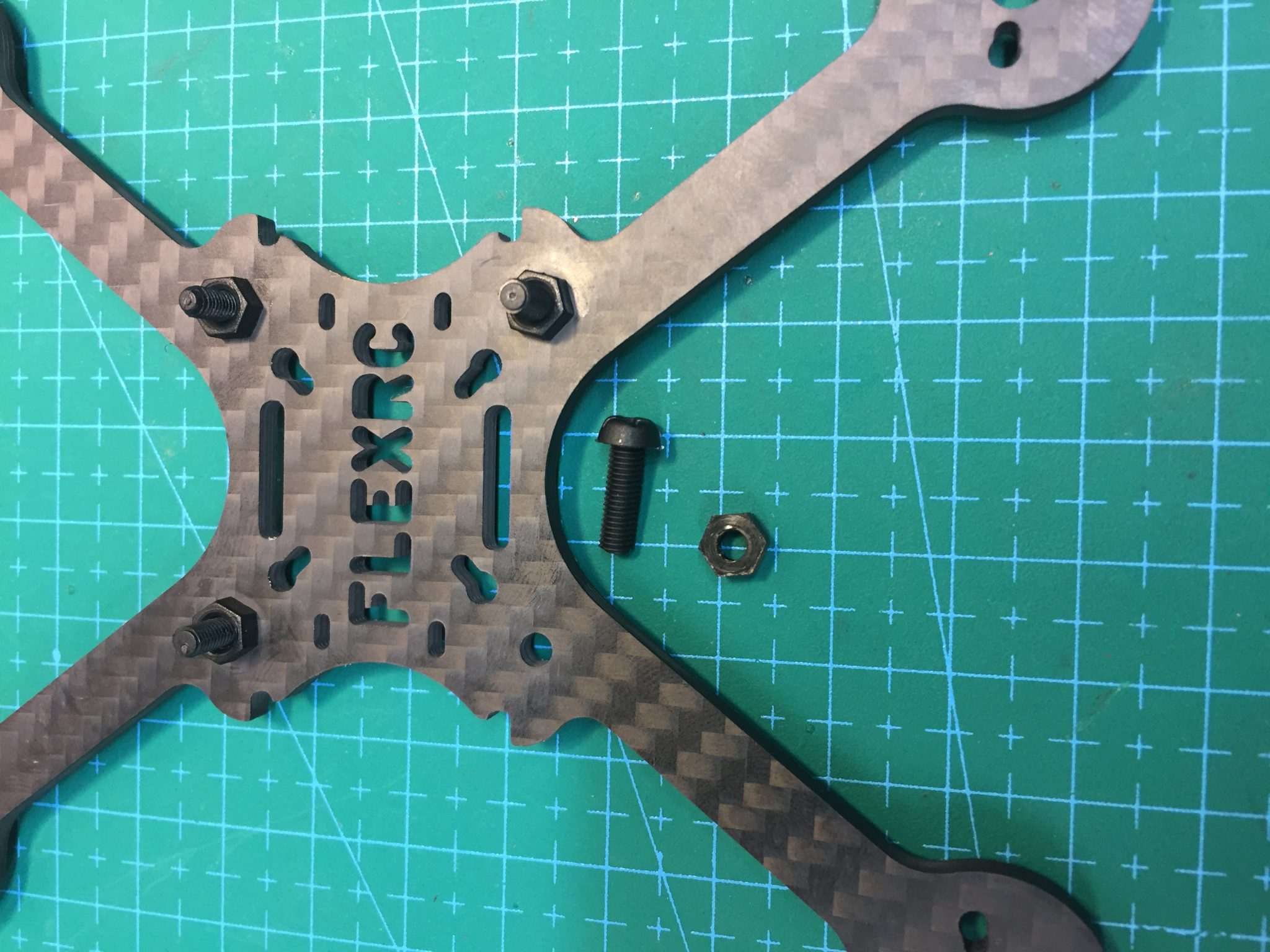
Begin by installing 4 short nylon screws and securing in place with nuts. The nuts will act as our spacers to keep the ESC off the carbon base plate. You can see from the photo that a single nut keeps the ESC barely off the base plate and will make our stack as short as possible.
TIP: If you are using a battery strap to secure your Lipo to the bottom of the main plate, now would be a good time to thread the strap through the slots in the main plate. It is much easier to install the strap before installing the ESC.
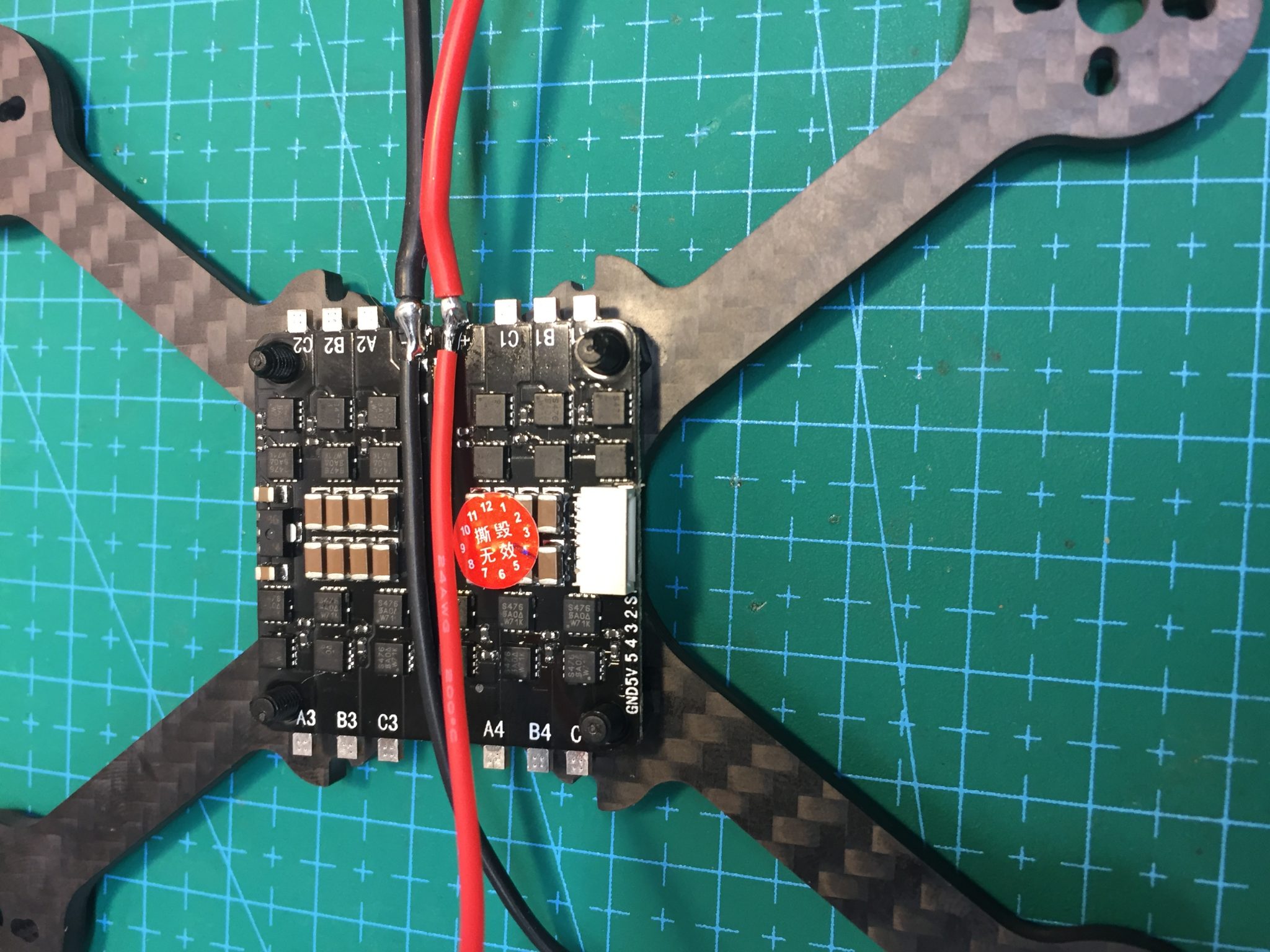
Install the 4-in-1 ESC on top of the nuts with the Lipo leads facing the rear of the quad.
Solder power leads for the Flight Controller to the Lipo pads on the ESC. I used 24 awg wire and left the leads about 3” long to give me plenty of room to work with.
Mount motors and connect to ESC
Because the Ascent 3” uses a 3mm base plate for added durability, the motor screws included with the T-Motor 1407 motors will be too short. FlexRC includes longer motor screws with the frame. Use these screws and mount the motors to the base plate.
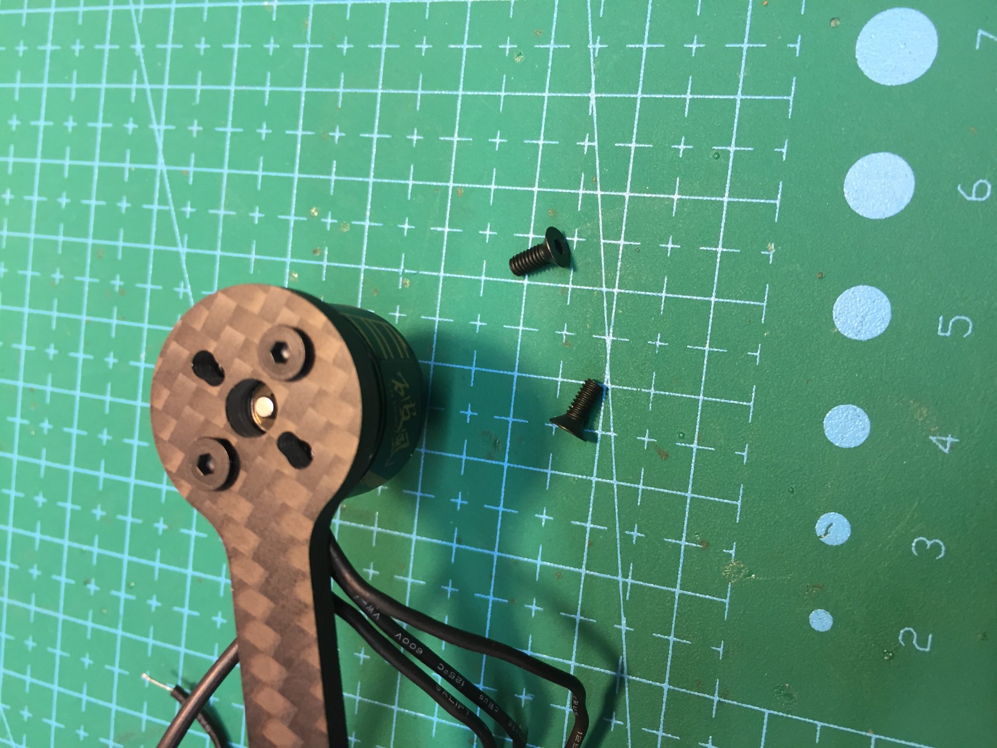
Measure and trim the motor wires and solder to the appropriate pads on the ESC. Using the Lipo leads as your reference for the back of the quad, note the motor numbering on the ESC, as it doesn’t follow standard Betaflight orientation. This isn’t a problem as we will simply connect the correct ESC signal wire to the appropriate location on the FC. Solder the motor leads to the nearest sets of ESC pads as shown.
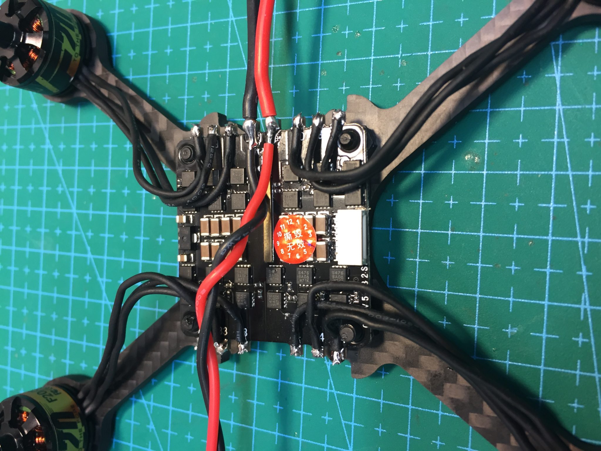
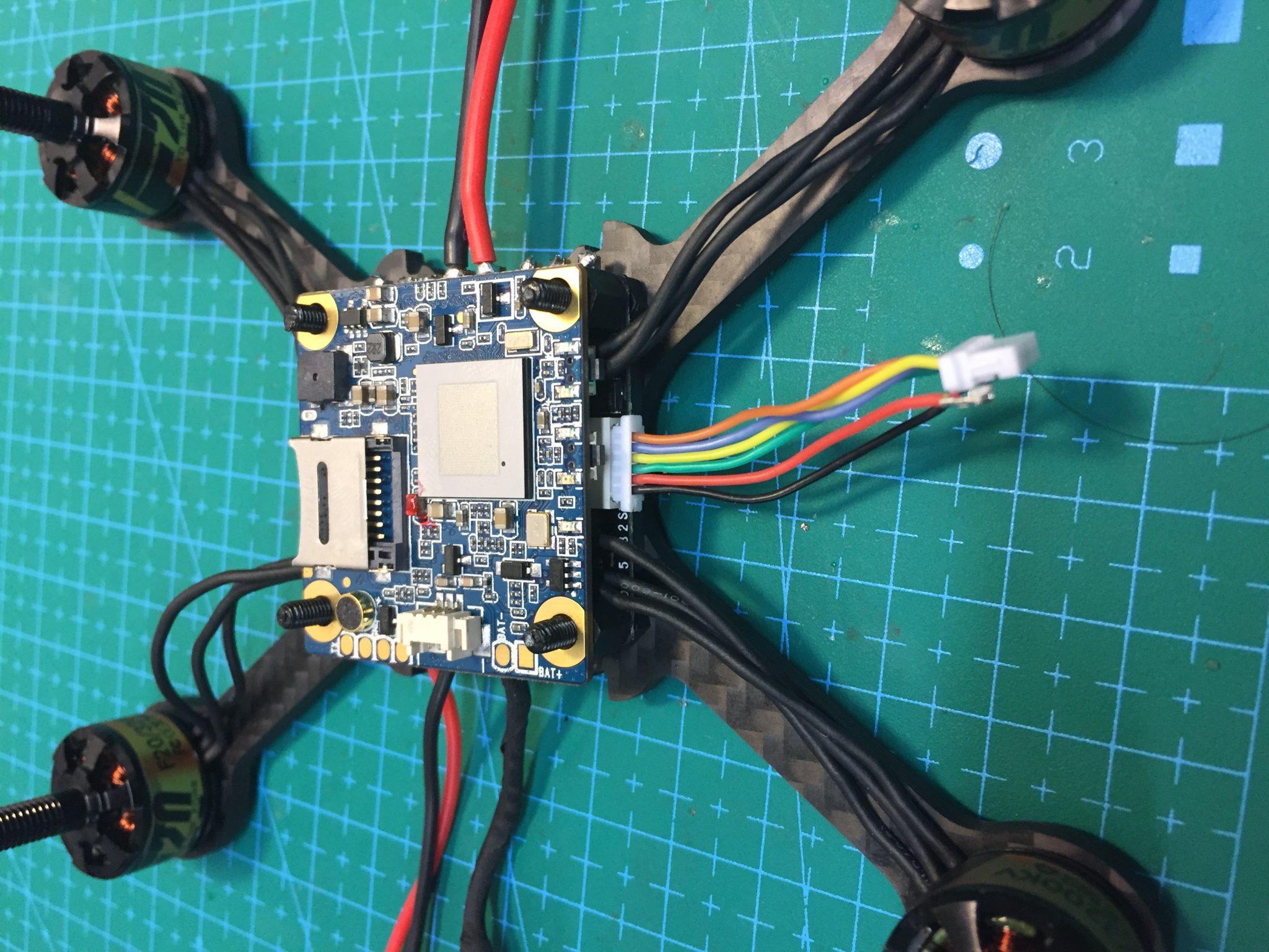
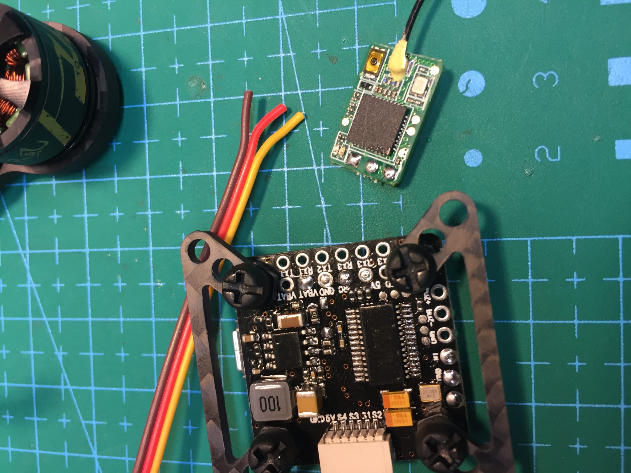
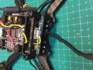
Install Runcam Split Board and power with ESC Signal Cable
If you are using nylon standoffs, install a set of 6mm M3 M-F nylon spacers above the ESC and place the Runcam Split board with the SD Card slot facing upwards. This will place the ribbon cable for the camera on the bottom of the Split board, running away from the Lipo leads towards the front of the quad.
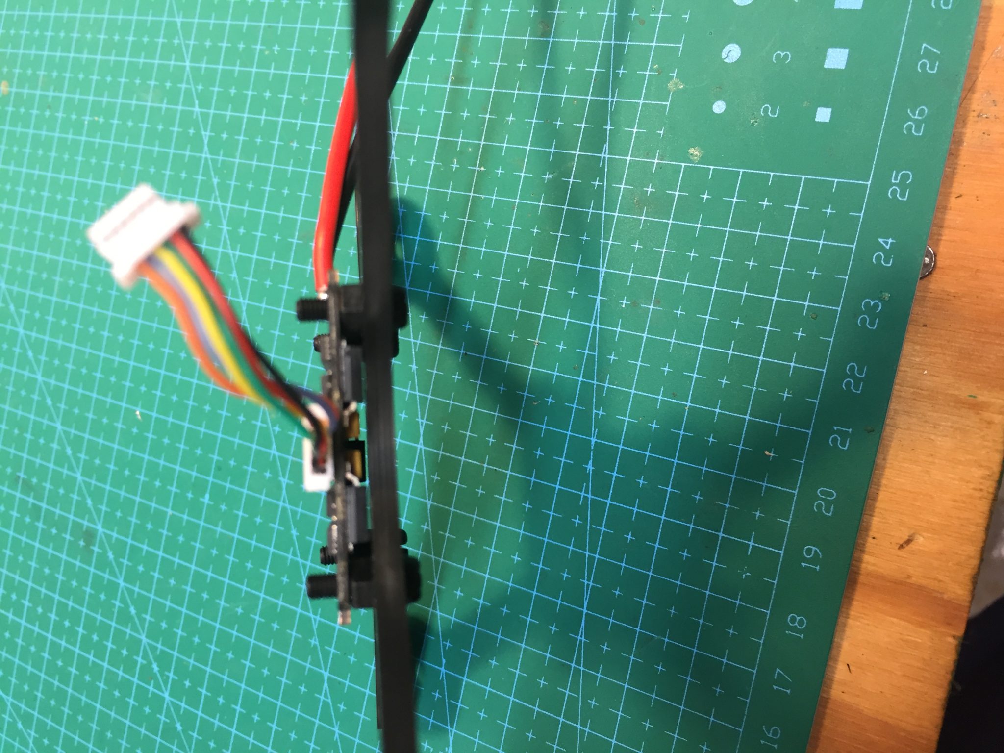
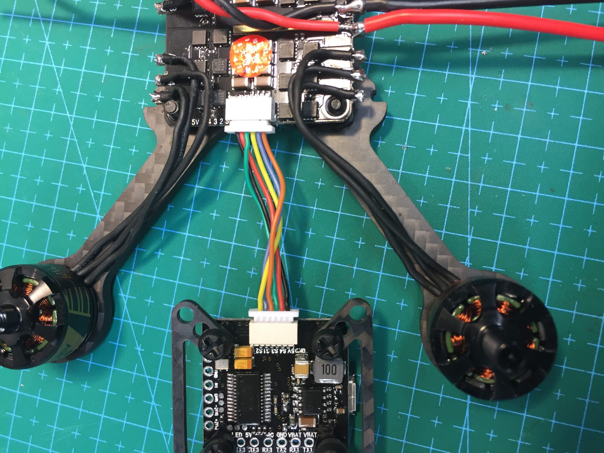
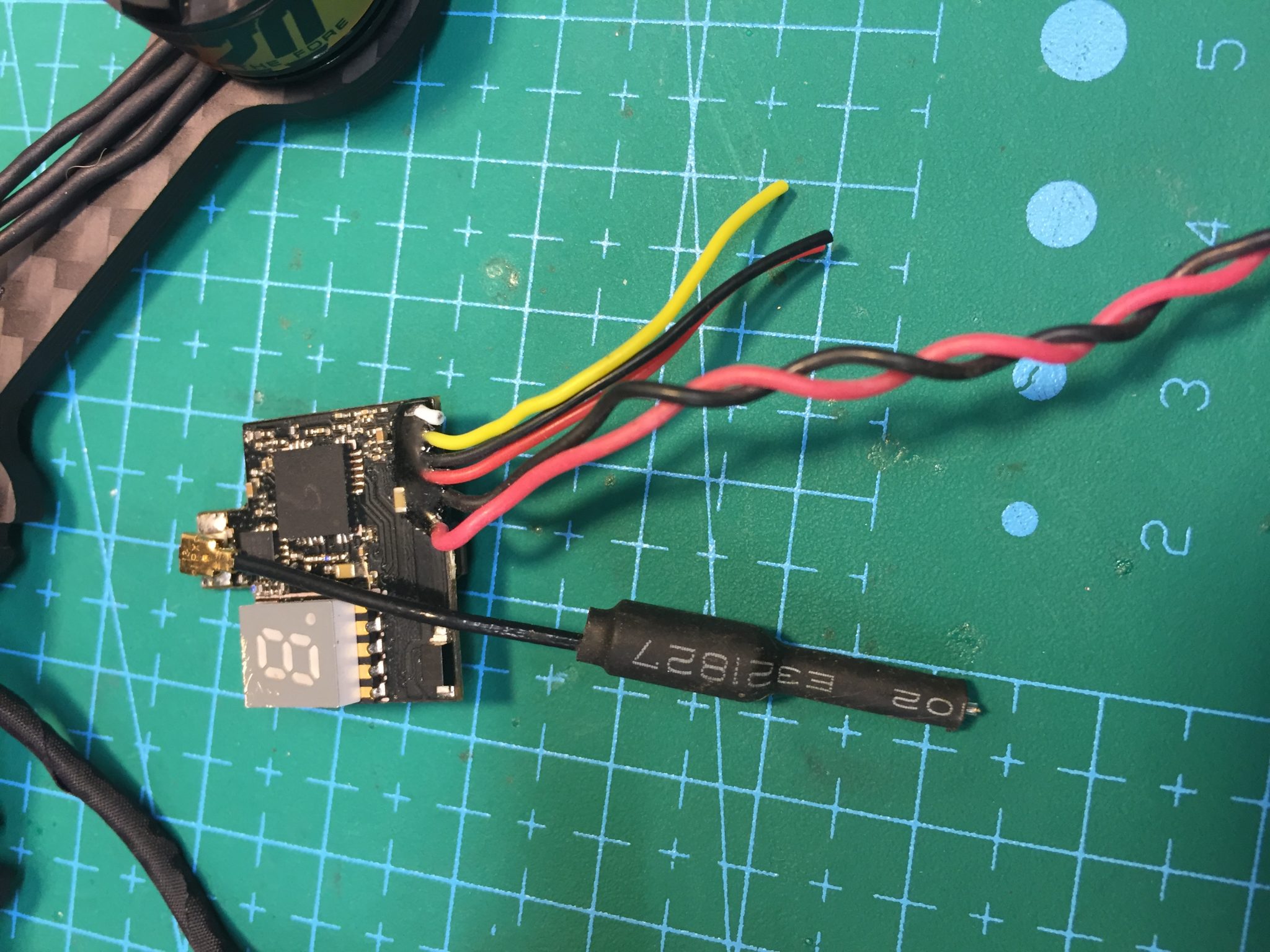
Find the ESC signal cable and plug one end into the ESC port. Because the Runcam Split requires high amperage 5v power, we are going to use the 5v and ground leads of this cable to power the Split.
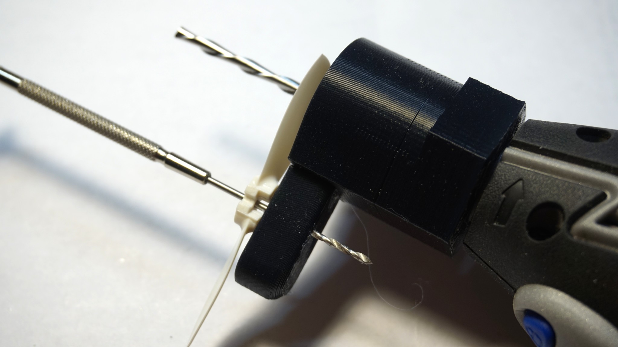
Hold the loose end of the cable (the end not plugged into the ESC) and locate the red and black wires. Using a knife blade or very small, thin screwdriver, lift the white plastic tabs securing the red wire and slide it out of the plastic plug. This may take a few tries but the wire should easily slip out of the plug once the tab is properly lifted. Repeat for all other wires. Note that we are removing all the wires, not just the red and black, because we need to change their order to match the ESC motor numbers. For now, just focus on the red and black wires.
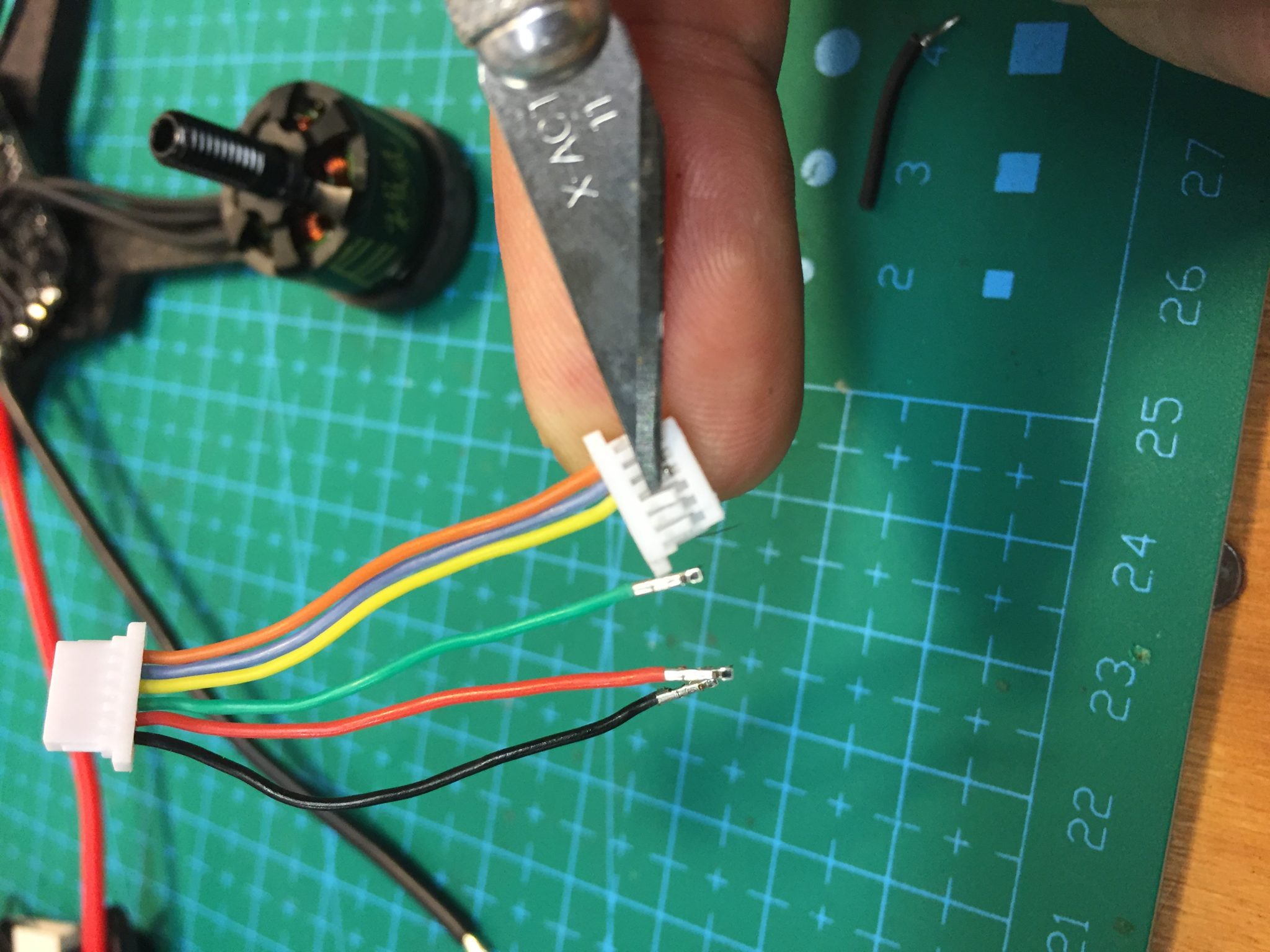
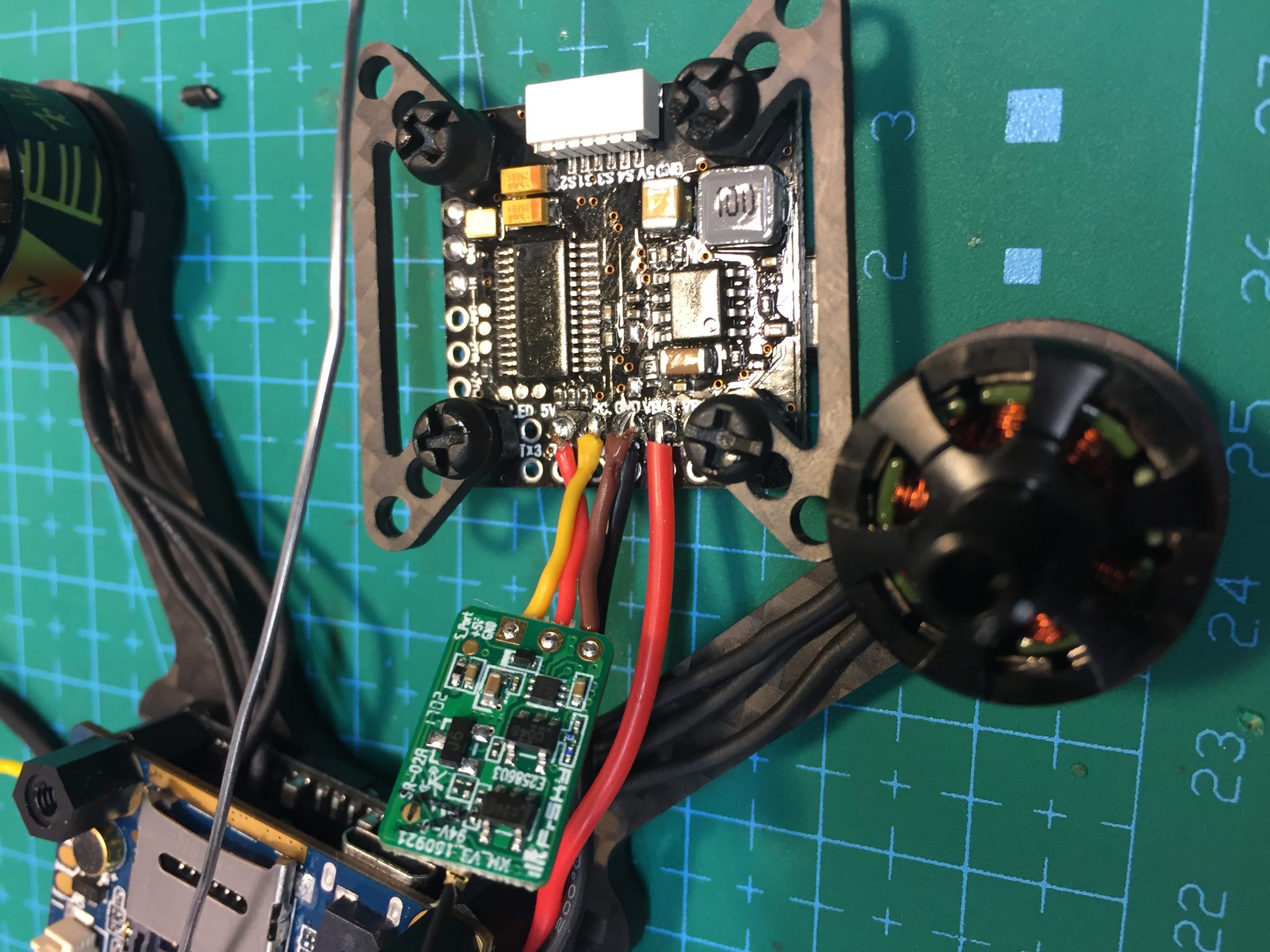
Cut the crimped ends off the red and black wires (DO NOT CUT THE CRIMPED ENDS OFF THE OTHER WIRES) and trim and tin them. Tin the +bat and -bat pads on the Runcam Split board (located near the front) and solder the red wire to the +bat and black wire to the -bat of the Split board. The Runcam split now has 5v, high current power.
Prepare the ESC Signal Cable
Next, we will rebuild the ESC signal cable to match ESC motor layout. We removed the 6 wires (red, black, blue, yellow, orange, green) from the loose end of the plug in Step 3. Now we will reinstall the ESC signal wires in the correct order in the plug.
The motor orientation is as follows:
| Position | BF Motor | ESC Pads | Wire Color |
| Left Rear | 1 | A2 B2 C2 | Blue |
| Left Front | 2 | A3 B3 C3 | Yellow |
| Right Rear | 3 | A1 B1 C1 | Orange |
| Right Front | 4 | A4 B4 C4 | Green |
Now examine the bottom of the flight controller and note the order of the wires as they are plugged into the white JST connector. From left to right, the connection order is GND, 5V, Motor 4, Motor 3, Motor 1, Motor 2. We are not using the 5V or GND wires so we only need to plug in the four signal wires in the correct order. As in the table above, the order, from left to right is EMPTY, EMPTY, green, orange, blue, yellow. Push the wires into the JST plug as shown. Ensure you have the plug oriented correctly and that the wires are pushed in correctly. When correctly pushed in, they will lock in place and cannot be removed without lifting the white tab again. If a wire will not lock in place, it is probably upside down. Flip it over and push it in again so the locking tab on the wire crimp aligns with the white tab on the plug.
Note: We will use Betaflight to test that the motors are wired correctly to the FC so if you make a mistake in the order above, it is very easy to correct.
Prepare the Flight Controller
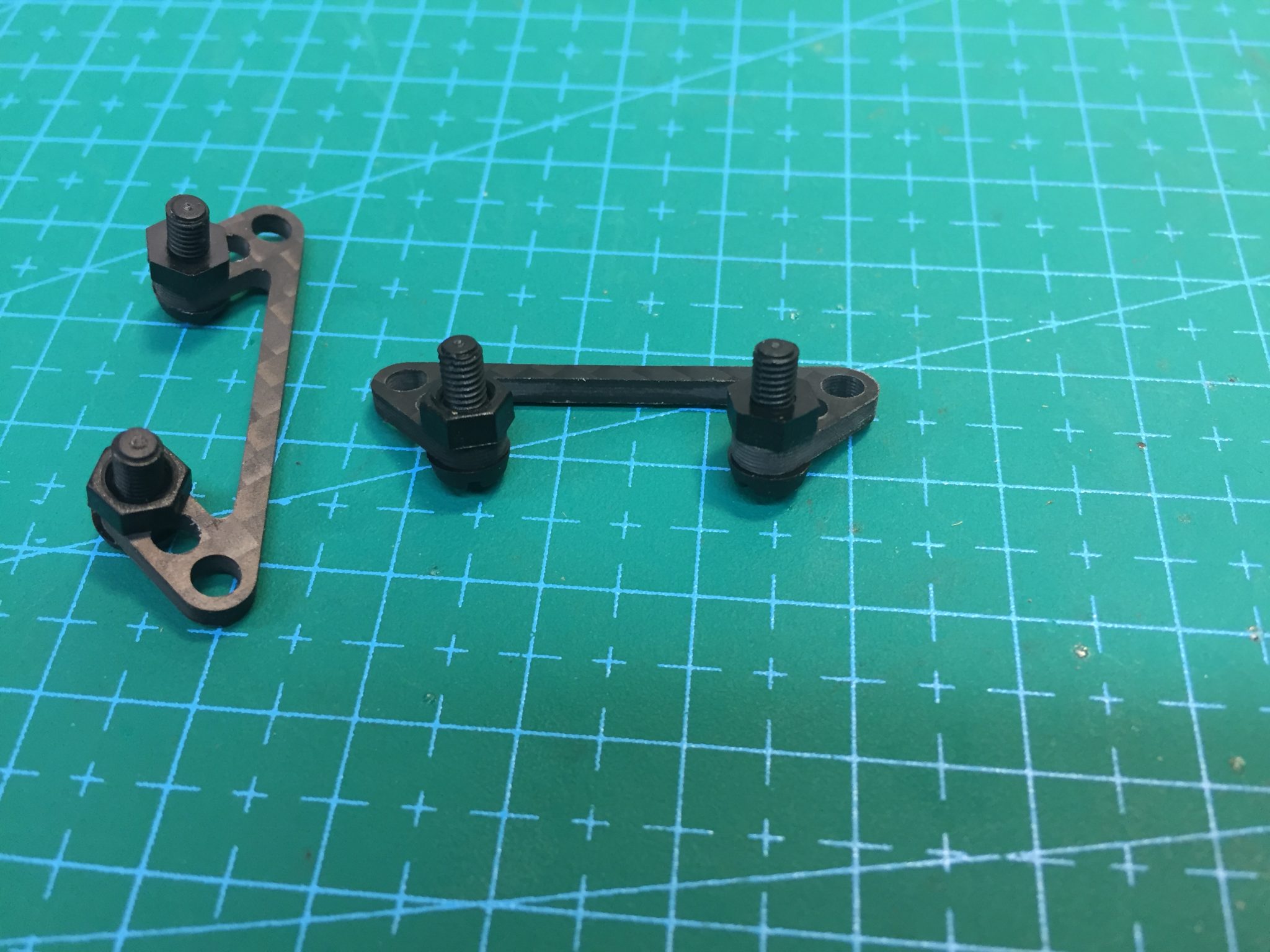
Because we are using a 20×20 flight controller above the 30×30 Runcam split board, we need to use adapters. The Ascent 3” Frame includes two different adapters, a one-piece “cross shaped” adapter and a two-piece adapter. We will use the two-piece adapter in this build.
Locate the two piece adapter, four short nylon screws, and 8 nylon nuts. Begin by installing a screw and a nut in each of the inner-most holes of the adapter. These nuts will act as washers to keep the FC from contacting the carbon.
Slide the adapters into the mount holes of the FC from the bottom, aligning the adapters so they are on opposite sides of the JST connector.
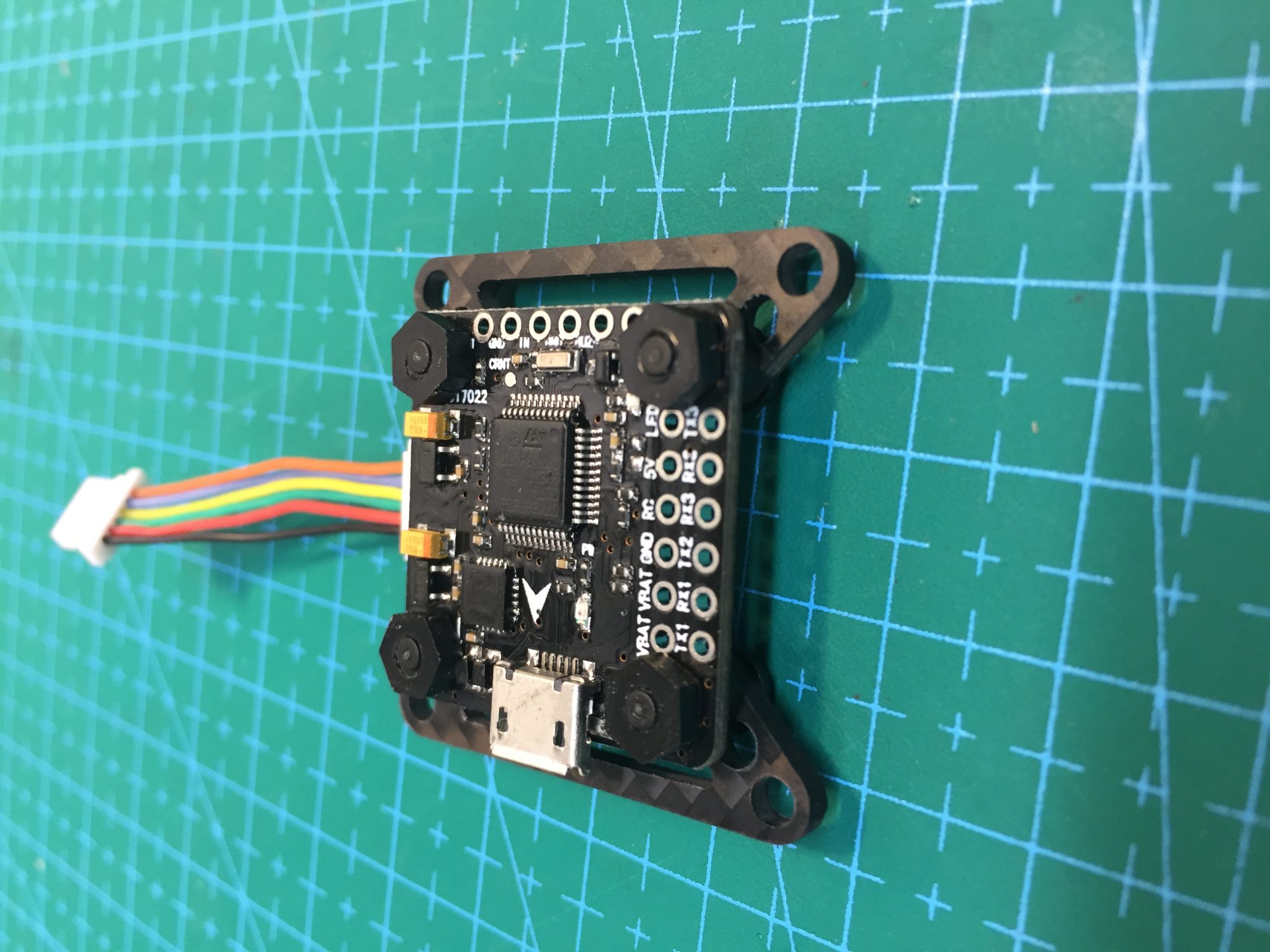
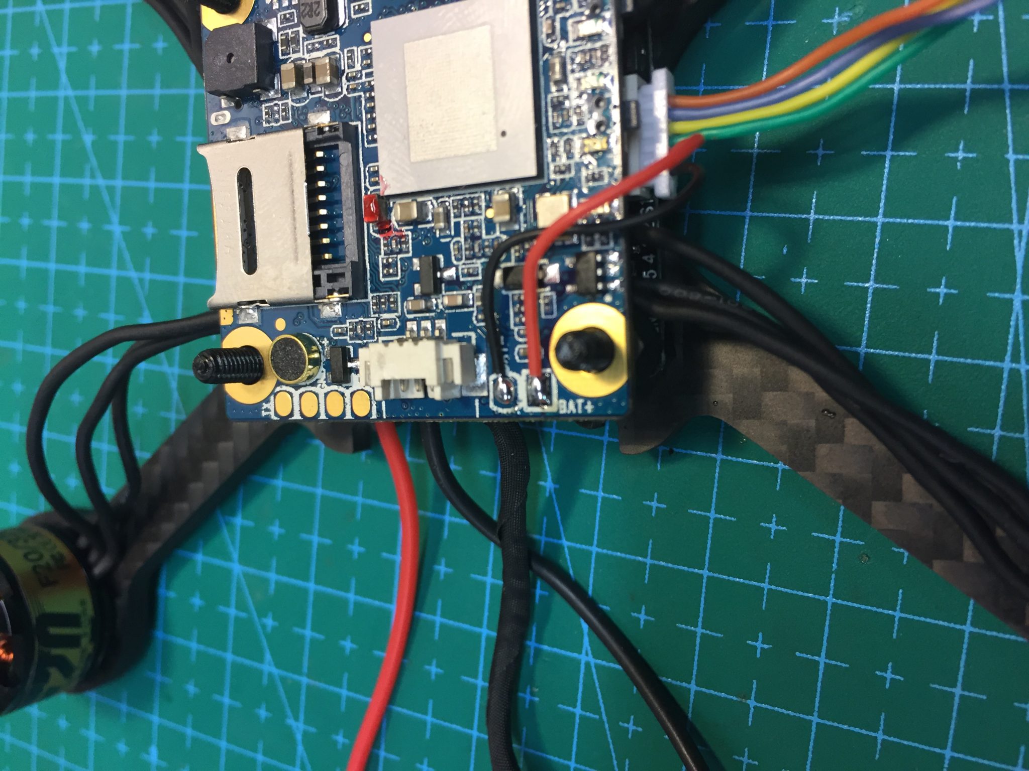
In this build, we are going to install the flight controller backwards, meaning the direction arrow in the FC is pointing to the rear) so that we have easier access to the USB port. We will adjust the board orientation in Betaflight to compensate for this alignment.
Locate the VBAT and GND pins on the port rail of the FC and tin the pin holes. Turn the flight controller upside-down and solder the Vbat leads from the ESC lipo pads to the bottom of the board appropriately. Double check to ensure you solder the positive lead to the VBAT pin hole and the negative lead to the GND pin hole. Use plenty of solder on the GND pin hole as we are going to use that pin as the GND for our receiver as well.
The FC now has direct Lipo power.
Install the Receiver
In this build, we are using a FrSky XM SBUS receiver. The installation for other 5v receivers is similar. For Spektrum or other 3.3v receivers, refer to the FC wiring diagram here https://flexrc.com/product/mini-f3-flight-controller-with-osd/
Still working with the FC upside-down, locate the 5V, RC, and GND pin holes. Note the GND pin hole is the same pin hole we used for FC Lipo ground. Solder short leads from the appropriate pin holes on the receiver to the appropriate pin holes on the FC. The receiver used in this build has a different pin order than the FC so ensure you are properly connecting 5v to 5v, GND to GND, and SBUS to RC.
NOTE: If your receiver pin holes align perfectly with your FC pin holes, you can use a 3-pin pin header to direct solder your receiver to the bottom of the FC. I prefer this method of installing the receiver but could not do that in this build because the pin holes are in different orders.
Once the receiver is properly wired to the FC, stick a small piece of double-sided foam tape to the bottom of the FC and then fold the receiver over to secure it to the bottom of the FC as shown.
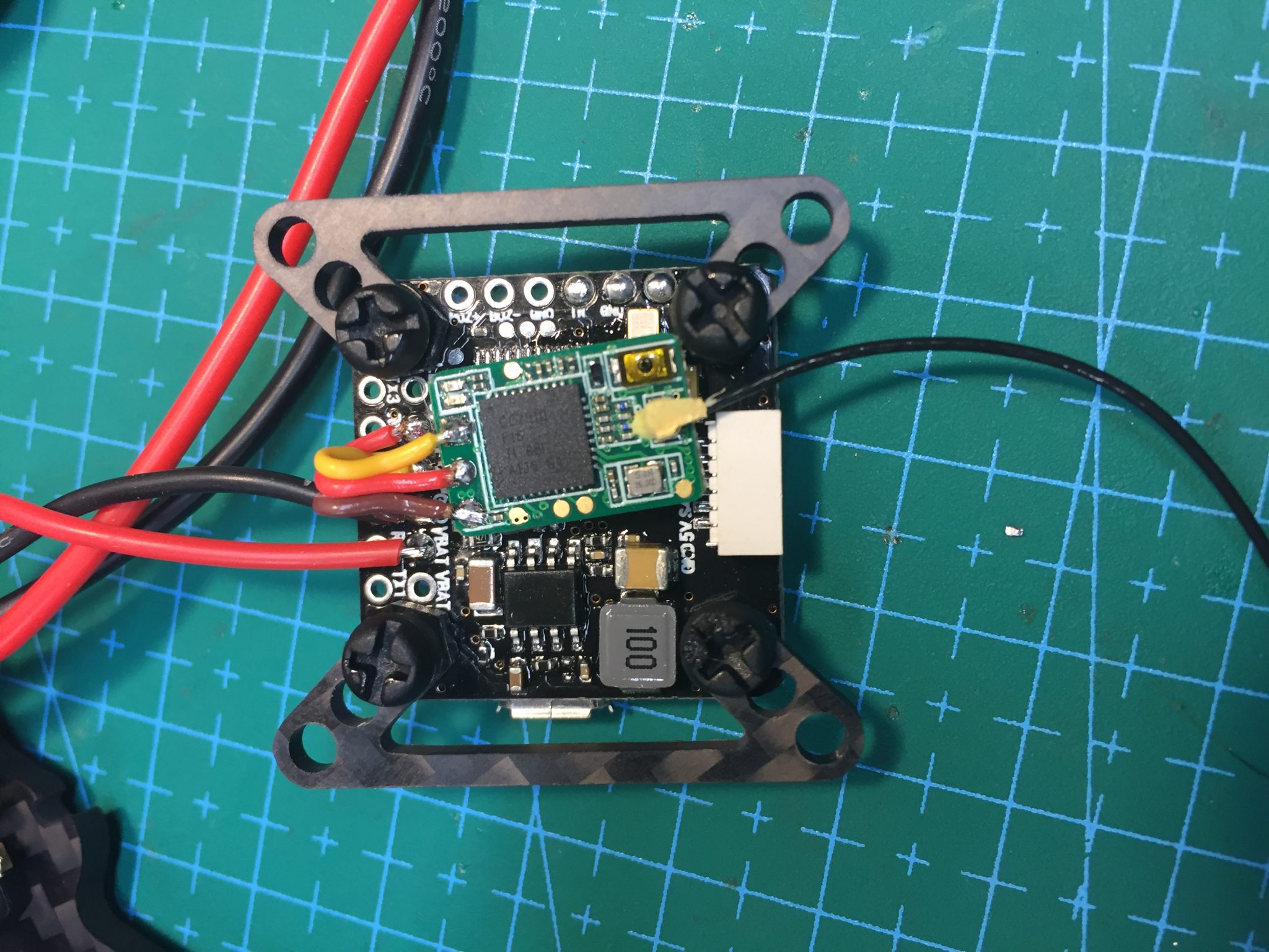
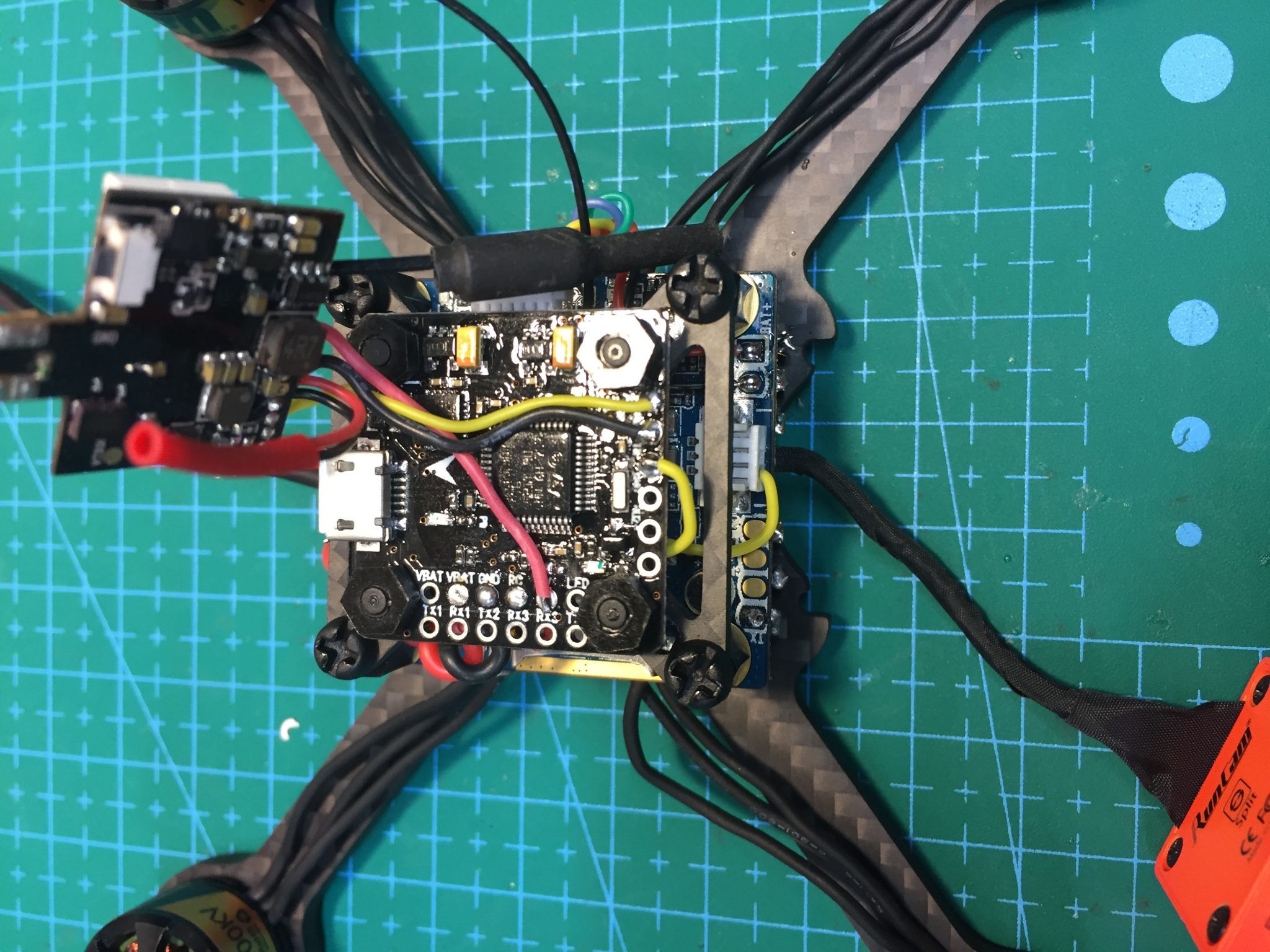
Mount the Flight Controller
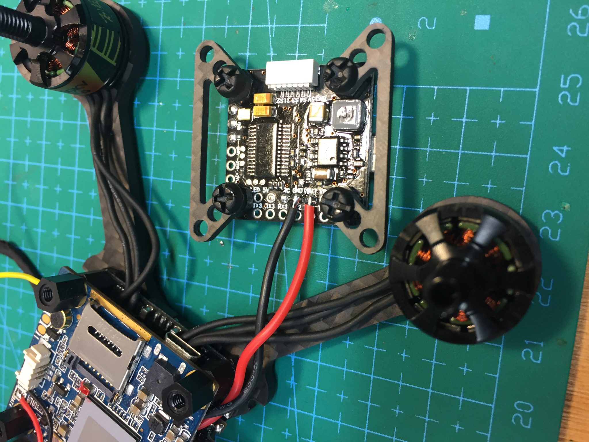
With the adapter, power wires, and receiver installed, we can now mount the flight controller. Install four 6mm M3 F-F standoffs onto the Runcam Split board. Turn the flight controller over and align it so the USB is facing the rear of the quad and the direction arrow is on top and facing the rear as well. Using short nylon screws to mount the FC assembly to the F-F standoffs. (NOTE: Ignore the loose yellow wire in the photo below)
The Flight controller is now secure on top of the stack.
Install the Video Transmitter and Connect to OSD
This build uses the Eachine ATX03 Super Mini 5.8G FPV Transmitter which has 6 wires: 5v in, GND, 5v OUT, GND, Audio, and Video In. The 5V out and one of the GND wires are intended to power the camera. Because our Runcam Split is powered separately from the ESC BEC, we do not need the wires. I also do not use the audio wire. I trimmed these wires a bit and protected them with shrink tubing.
Identify, the remaining three wires, 5V in, GND, and Video in and trim and tin them. Solder the 5V in to the 5v pin hole on the FC. Note this is the same pin hole we used for the reciever power on the other side of the FC. Solder the GND and Video In to the OSD rail on the side of the FC as shown. The Video In wire from the vtx goes to the OUT pin hole of the FC, which is the pin hole on the far right of the OSD rail. Again, Video OUT from the FC go to Video IN on the vtx.
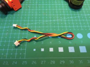
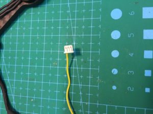
Next, we need to bring the video signal from the Runcam Split board to the FC OSD. To do this, locate the 3-wire video cable that comes with the Runcam split and, using the same method we used for the ESC signal cable, remove all the wires except the yellow one. Leave one end of the yellow wire in the JST plug and trim the other end. Trim and tin the end of the wire, plug it into the JST on the Runcam Split board, and solder to the Video IN.
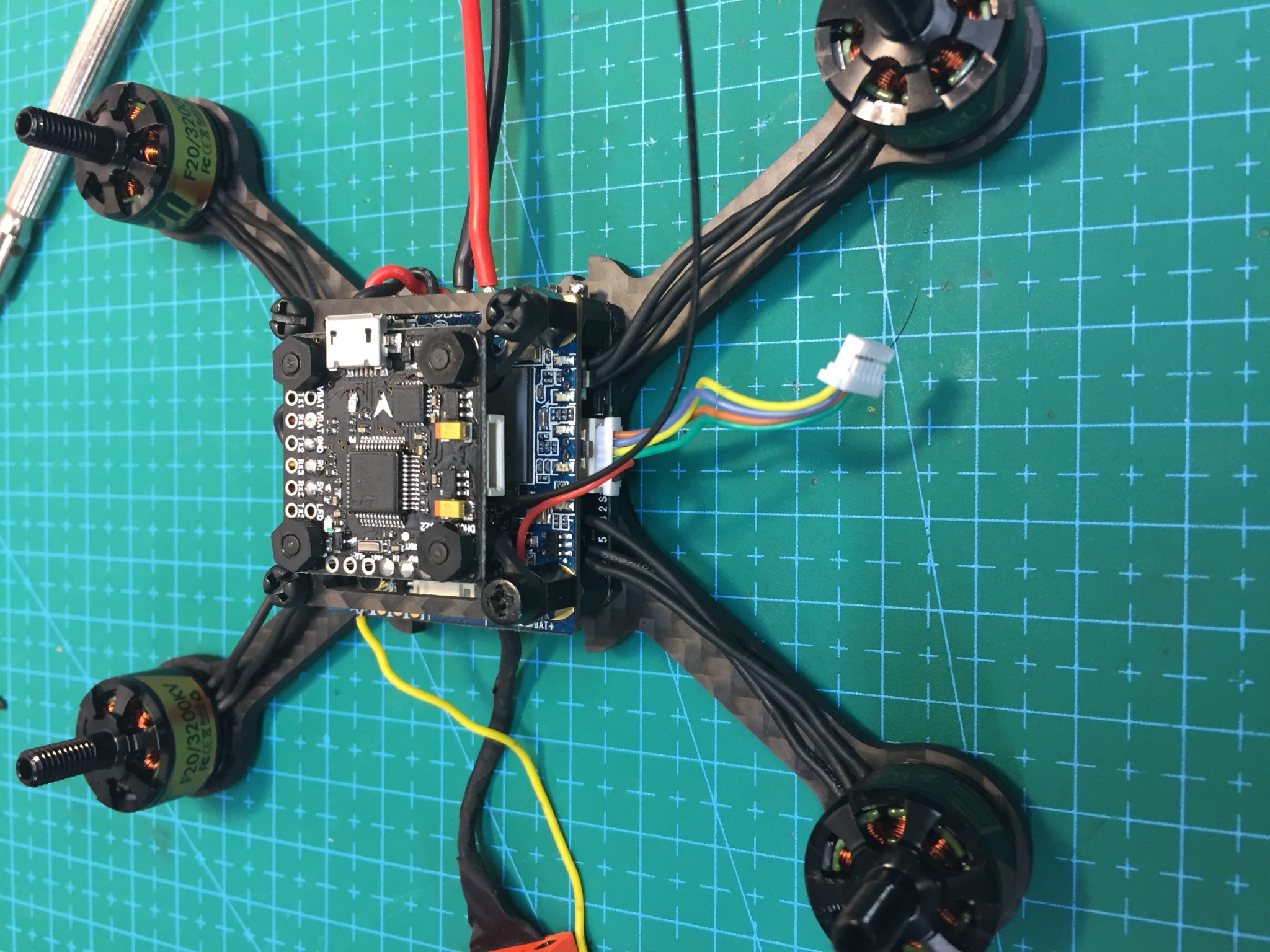
Use some double-sided tape on top of the FC and fold the VTX over to secure it, similar to how we secured the receiver to the bottom of the FC. I also added a slightly loose cable tie around my VTX and FC to ensure it didn’t come off in a crash. Don’t over-tighten this cable tie as it could easily damage the FC or VTX. Make it just tight enough to prevent the VTX from lifting off the FC. A flexible wrap-strap would work as well.
The FPV system is now installed. In summary, the video signal leaves the Runcam Split board via the single yellow wire in the JST plug and is connected to the IN pin on the OSD rail of the FC. The signal leaves the OUT pin of the OSD rail and is sent to the input wire of the vtx to be broadcast to your goggles.
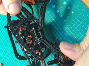
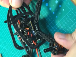
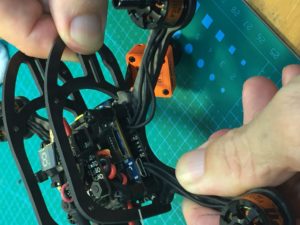
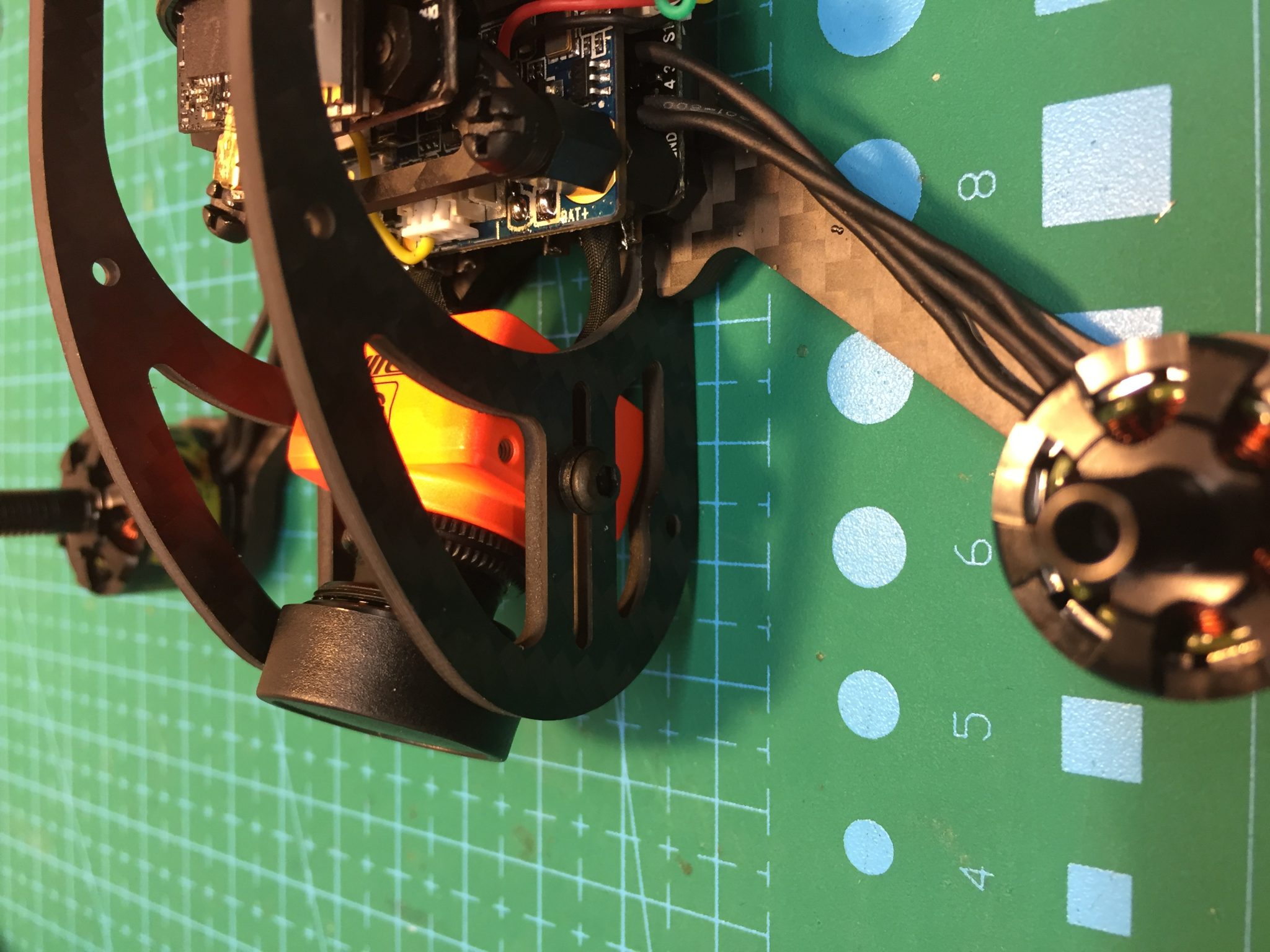
Install the Roll Cage, Runcam Camera and finish the build
The Roll Cage plates easily install onto the frame without hardware. They can be installed and removed with the component stack in place. To install a roll cage plate, slip the rear notch of the plate over the rear motor arm and fit the notch into the matching notch on the base plate plate. Gently pull the cage forward, which will slightly bend the cage and allow you to slip the forward notch of the cage over the front notch on the base plate. Repeat for the other roll cage plate.
Locate two small hex screws in the hardware kit that comes with the runcam split and the 2 nylon washers. Position the Runcam camera between the roll cage plates and align the screw holes of the camera with the long horizontal slots in the cage. Install the screw and nylon washer on each side loosely. Position the camera to your desired angle and tighten the screws. The nylon washers help ensure the camera will not move in a crash.
Install three aluminum standoffs between the roll cage plates and secure with the included screws.
You can certainly install fewer standoffs to save weight if you desire.
Finish the build by securing the receiver antenna as desired. Tape the motor wires to the base plate arms to ensure they are not pulled from the motors in the event of a crash into tree branches or brush. Add velcro, foam tape, or a rubber pad to the bottom of the frame if desired to keep the Lipo battery from sliding. Install battery strap if not installed previously.
Set up Flight Controller
REMOVE THE PROPELLERS. Plug the FC into a PC using a USB cable and launch the Betaflight configurator. This guide will not cover the complete Betaflight setup as you can instead refer to the Bare-Bones Betaflight Setup Guide. In addition to the bare bones setup, there are two things to check in Betaflight that are specific to this build.
First, ensure the motors are connected properly to the Flight Controller. In the Motors tab, ensure you do not have propellers installed and click the slider to confirm. Plug in a Lipo battery and move each motor slider to ensure that the appropriate motor spins. Also ensure that each motor rotates in the right direction.
If the wrong motor spins when a slider is moved, simply unplug the 4-wire ESC signal cable and reposition the wires correctly per the table in Step 4.
If a motor does not spin in the correct direction, use the BLHeli configurator to reverse it.
Final Comments
You will note that the Runcam Split has two control buttons on the board and, unlike a standard FPV cam, it must be turned on each time you plug in a battery. The buttons also allow you to control the recording functions. These functions can all be controlled remotely via the radio by simply connecting the TX, RX, and GND pads of the Runcam Split board to a free RX, TX, and GND pad on the Flight controller and then setting up the port and modes in Betaflight. This process is covered in detail on the Runcam website. (LINK)
If you desire to use a Runcam Micro instead of a Runcam Split, you will need spacers between the camera and the roll cage plates and the micro is narrower than the Split.
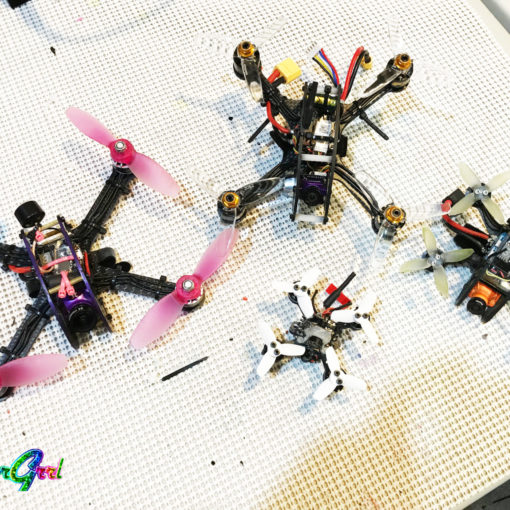
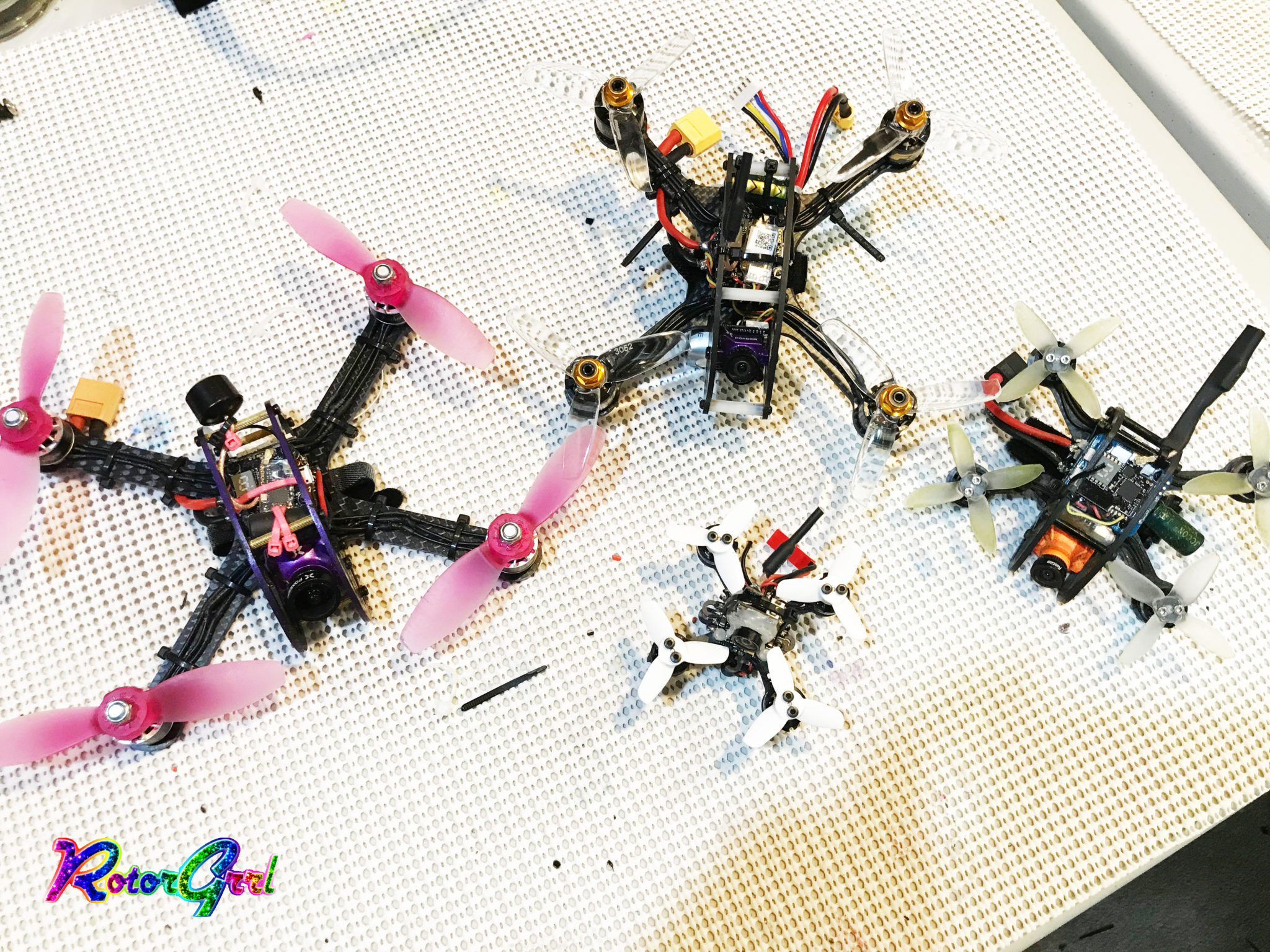
A wide range of hardware can be used with the Ascent. A full 3-high 30×30 stack (ESC, Flight Controller, Split board, etc.) will easily fit within the roll cage plates. The base plate also has holes for a full 20×20 stack for an even lighter build.